The Armstrong 222/221 amplifiers
The 221 and matching 226 receiver were introduced in 1965, and were launched at the Audio Show that year in London at the Hotel Russell. The picture above shows the front of a 221. The most obvious visible difference between this and a 222 is the row of three pushbuttons. The power sections of this amplifier were similar to the 222's. However this amplifier was unusual in being a transistor/valve integrated hybrid. It had a pick-up input for magnetic cartridges (sensitivity of 3·5 mV) in addition to the ceramic pu input. It also had tape output and monitoring facilities. The three push buttons were the tape monitor switch, a treble (scratch) filter switch, and a loudness control. In effect the 221 was a 222 to which some of the features of the 225 had been added.
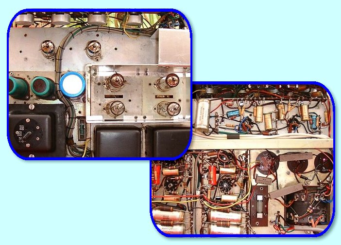
The above shows views of the inside of the 222, seen from both from above and from below. One feature of the 200 range which would now be regarded as very unusual was the the input switching that was built into the phono sockets. These were arranged to provide ‘automatic’ mono/stereo switching for some inputs. When just one phono plug was inserted it was connected to both channels in parallel, thus providing double-mono output using both power amplifier channels and loudspeakers. However, when a second phono plug was inserted into the other socket it operated a switch that broke the parallel link and the two channels then acted as a normal stereo pair. This feature was useful at the time since when the 200 range came into service most available signal sources were monophonic.
The above shows the circuit diagram for the power amplifier used in both the 222 and the 221. This used a pair of ECL86's (V3 and V4) with their triode sections employed as the input voltage amplifier stage and inverter stage. Their tetrodes were used as the basis for the push-pull output. The switch shown that can be used to place a 330kOhm resistor in parallel with the input 1 MegOhm resistor acted with the input capacitor as a rumble filter. This rolled away the low frequency response to filter rumble if the amplifier was used with a poor turntable. The power line voltages V1 and V2 shown were both approximately 265Volts and were supplied from a solid-state power supply that used a pair of RS240AF rectifier diodes arranged as a voltage doubler. The heater supplies are omitted from the diagram which only shows one channel of the pair provided for stereo.
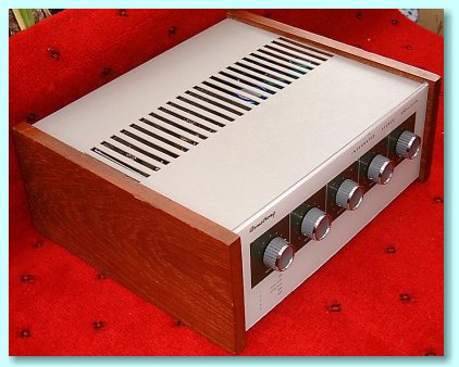
The photograph above shows a general view of the external appearance of a 222 amplifier. This gives a good impression of the styling as well as showing the slots provided for air circulation to cool the valves.
Colour photographs on this page
© Mick Broadhead of Good Hi-Fi
Used by kind permission.
 Content and pages maintained by: Jim Lesurf
using HTMLEdit and TechWriter on a StrongARM powered RISCOS machine.