The Armstrong 421 Amplifier
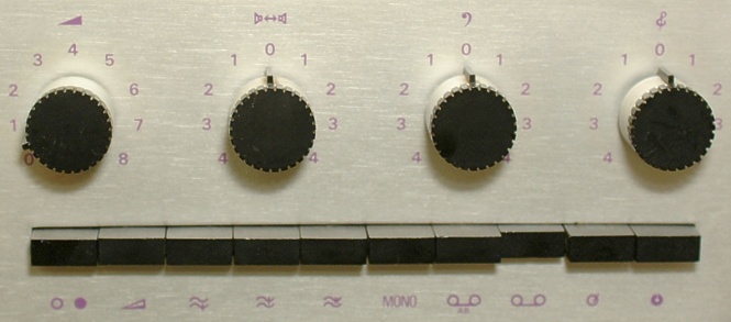
The above image is a close-up of the central section of the front panel of a 421 amplifier. This makes it easier to see the detailed appearance of the purple lettering and the black controls against the anodised brushed aluminium finish of the facia. The 421 amplifier (also used in the 425 and 426) was sometimes described as being capable of over 20 Watts per channel as this level was obtainable into 8 Ohm loads at 1 kHz.
Usually, Armstrong described the rated power output of the 400 amplifier as being 15 Watts per channel as this was the power that could be delivered into any resistive load between 4 and 16 Ohms. This was in line with the contemporary practice for valve power amplifiers. However most valve amplifiers employed an output transformer with a choice of tappings. This ensured that a similar power could be obtained into various loads. As the 400 was a transistor amplifier with no output transformers, it could deliver more power into an 8 Ohm load than into either a 4 or 16 Ohm load. It was also occasionally described in magazines as using silicon transistors, although the output devices were AL102's which were germanium.
400 Range amplifier specifications
| Rated Output
| >15 Watts (any impedance from 4 to 16 Ohms)
|
| Frequency Response
| 20Hz - 20kHz -1dB
| Distortion
| <0·5% at 15Watts
|
| Input sensitivity
| pickup 60mV (xtal) / 3·5mV (mag)
| radio 100mV
| tape 400mV
|
| Noise
| -55dB (pickup)
| -60dB (radio)
| -70dB (tape)
|
The amplifier also had a 400mV output for tape recording, and a stereo headphone socket. As with many other Armstrong ranges, the tape outputs came via the tone controls and filters. Hence what was recorded could be altered in a controlled manner if this was required. This particular feature proved quite popular at the time with many people who made tape recordings.
As well as Volume, Balance, Bass, and Treble controls, the 421 had the following controls:
- Rumble Filter: -5dB point at 30Hz
- Treble Filter 1: -3dB at 6.5kHz, -25dB at 10kHz
- Treble Filter 2: -3dB at 4.5kHz, -40dB at 9kHz
Treble Filter 2 was specifically designed for use with AM radio. Thus it gave a reasonably flat response up to about 4kHz, but introduced a strong attenuation at 9kHz which was the most likely beat frequency to cause audible whistles when listening to AM.
There was also a ‘loudness’ switch which introduced a contoured reduction in level as was popular at the time. This reduced the signal level by 20dB at 1kHz, but the levels at low and high frequency were not reduced as much, so as to (relatively) lift the response by +10dB at 70Hz, and +5dB at 10kHz.
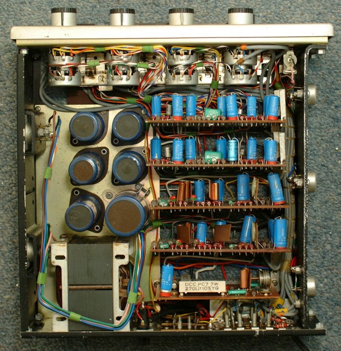
The above picture shows a top view of a 421 with its case removed. Apart from the facia, the appearance is almost indistinguishable from a 521, and the board/component layout of the two are the same.
Colour photos on this page © J. B. Lovelock.
Used by kind permission.
 Content and pages maintained by: Jim Lesurf
using HTMLEdit and TechWriter on a StrongARM powered RISCOS machine.