The Armstrong A20 and PCU25


The A20 was Armstrong's first ‘Hi Fi’ stereo power amplifier unit. Previous power amplifier chassis had been monophonic, although these could be used in pairs with a suitable stereo control unit to obtain stereo operation. The company had made previous stereo ‘radiogram chassis’ (what we might now refer to as a tuner-amplifier or receiver), but had not produced a stand-alone stereo power amp until the A20.

A20pic.jpeg - 47Kb


The above image shows a photograph of an A20 that was used for publicity purposes at the time the design was manufactured.

Specifications for A20
Rated Output 12 Watts (Output transformer tappings for 4, 8, and 16 Ohms)
Peak Output25 Watts per channel
Stability Margin 20dB with rated resistive load. 15dB with 0.1 microF shunt load.
Frequency Response 15Hz - 22kHz within 1dB Distortion <0·1%
Power Response 20Hz - 18kHz within 1dB Channel Matching within 1dB
Input sensitivity 410 mV for 12 W output Output Valves EL84 ultra-linear’s
Noise -85dB Feeback 29dB
Damping Factor 53 Transient Response 4 microsecond rise-time
Crosstalk -52dB at 1kHz. -40dB at 10kHz. Power Consumption 110 W (inc PCU25)


The above table lists the basic performance parameters for the A20 power amplifier unit. The valves used were GZ34 (rectifier), 3 x ECC83, 4 x EL84. The literature provided at the time included the following information:

PCU25pic.jpg - 42Kb


PCU25logo.jpeg - 7Kb 
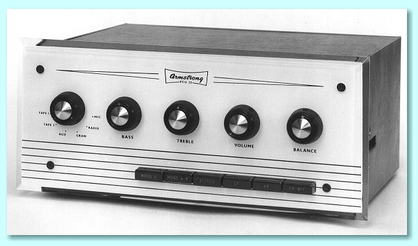
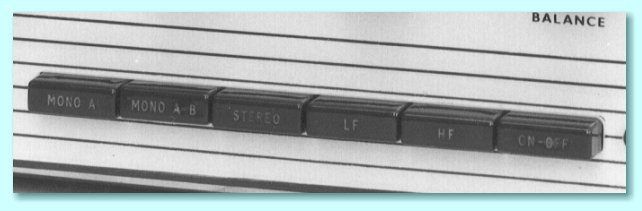
The above photo shows the PCU25 pre-amplifier (control unit) that was recommended for use with the A20. Armstrong adopted a new external styling at the start of the 1960's with a white perspex facia with lines and legends in black. Cases were in what was described in adverts of the time as “an attractive maroon vinyl-hide covering”.

The same style of facia was used for the tuners, and a number of other units of the time, including the Mk 2 version of the Stereo 12 radiogram chassis

The PCU25 provided the following inputs:

The sensitivities given above are the input levels required for 410 mV output - i.e. the level which will produce 12 Watts per channel from the A20. The nominal frequency response in each case is 20Hz - 20kHz ±1dB.

The PCU25 was rated to give less than 0·1 percent distortion for 410mV output for any settings of the tone controls. Cross-talk was -48dB at 1 kHz, and -30dB at 10kHz. 400mV low impedance outputs were also provided for output to a tape recorder. The valves employed were 2 x EF86 and 3 x ECC83. In the original literature provided with the unit, the circuit was described as follows:
In addition to the Volume and input selector, the controls provided were:
PCU25buts.jpeg - 22Kb


There were also push-button selectors for:
When the Rumble filter button was pressed in, a high-pass filter was applied with a nominal roll-off of 6 dB per octave based on a turn-over frequency of around 80Hz. The action of the Treble filter button was more compex. When this button was pressed in it altered the behaviour of the Treble control knob. The Treble control then altered the slope and turn-over frequency of a variable low-pass filter. With the Treble control “at 12 o'clock” the filter had a nominal turn-over frequency of 9kHz and a slope of 12dB per octave. Adjusting the Treble control then applied more or less filtering.

FRgraph.gif - 20Kb


The above graph illustrates the actions of the filters.

The PCU25 was designed as a relatively ‘no frills’ unit. Those wanting every available feature would be recommended to buy the more expensive PCU27.

If you wish to see a detailed circuit diagram of the PCU25 click here.


back.gif - 204 bytes homeblue.gif - 1289 bytes next.gif - 203 bytes
Click on the logo to return to the home page.


Content and pages maintained by: Jim Lesurf
using HTMLEdit and TechWriter on a StrongARM powered RISCOS machine.