oblogo.gif - 28Kb


Brief Details of some early Armstrong items


This page summarises information on a number of the earlier valve-based amplifiers, tuners, radios, etc, that Armstrong made. In many cases the information I currently have is very limited, and some of the details may be incorrect. There are also probably many units which I am currently unaware of, so have not listed. If you have documents, circuit diagrams, magazine reviews, or photos relating to any of the following, or relating to Armstrong units I have not mentioned, I would be delighted if you would let me know and perhaps have a copy so I can add data to these pages! My email address is at the foot of each page.


St55pic.jpeg - 25Kb

The above shows the picture on the front cover of the booklet of the
INSTALLATION & OPERATING INSTRUCTIONS AND SERVICE DATA
for the Armstrong Stereo 55 tuner-amplifier chassis.

During the 1940's and 1950's these guidebooks were mostly written by C. C. Jackson
and Ron Sheppard and were supplied to owners with the set they purchased.


In a few cases I have more extensive information on a unit than is summarised here and will add a detailed page on each of these as I can. For now, I have just added links from the table, below, to paragraphs further down this page. The items are listed here in alphabetical order as I do not have reliable dates in many cases.

Model Numbertypedatespowero/p valvesbands
AF105mono am/fm tuner-amp??EL84vhf/mw/lw/2sw
AF208mono am/fm tuner-ampc19605WEL84vhf/mw
AW73all waveband radio c19406W6V6sw/mw/lw
AW93all waveband radioc19406W6V6sw/mw/lw
BS54mono bandspread radio----
BS125mono bandspread radio----
EXP53mono radio---sw/mw/lw
EXP73All waveband radioc19508W--
EXP119mono bandspread radio---7sw/mw/lw
EXP125/3mono radioc195015W-3sw/mw/lw
FC38mono radio19538WEL84sw/mw/lw
FC48mono radioc19508WEL842sw/mw/lw
FM56mono radio???vhf/?
Jubilee Mk 2mono radioc19608W-vhf/mw/lw
PABOpreamp bias oscillator?---
PABO3preamp bias oscillator?---
RF41mono radioc195010W-sw/mw/lw
RF103/3mono tuner-amp1950?6P25sw/mw/lw
RF104mono radioc1950---
SS10superhet/TRF radioc1947--sw/mw/lw
ST3tunerc1960--lw/mw/vhf
Stereo 12stereo tuner-amplifierc19528WEL84vhf/mw/lw
Stereo 12 Mk 2stereo tuner-amplifierc1954-EL84vhf/mw/lw
Stereo 44stereo tuner-amplifierc19514WEL84mw/lw
Stereo 55stereo tuner-amplifierc19525WEL84vhf/mw
T4BVHF tunerc1960--vhf
Tele-GramTV and record playerc195314 inch CRT--
TV 5TV Consolec195314/17 inch CRTs--
TV 15Television Chassisc195212 inch CRT--
TV 20Television Chassisc195012 inch CRT21 valves-


Some more details of selected items


AF105

AM/FM tuner-amplifier. 2sw/mw/lw/vhf bands. Front panels with large glass dial. Push-pull output, using EL84 valves, with one valve driven by the other. It used permeability tuning for the VHF section, and combined IFs. Full of 0.01microF ceramics to keep it from taking off. The AF105 was the first Armstrong set that had VHF built in. Similar chassis to FC48. essentially it was an FC48 with the FM section added. The spindle of the gang-tuning capacitor for the AM bands of the FC48 design was extended and a nylon cord wound around the end. This was then attached to the slugs in the VHF tuning coils and pulled against springs to adjust the slugs hence tuning the VHF sections.

AF208

AM/FM tuner-amplifier (radiogram chassis) mw/vhf bands. Output used a single EL84 in single-ended mode. Tape input/output and tone controls as well as volume. Two pickup inputs. 30 - 22kHz ±2dB. 15dB feedback. 7 Valves. 5 Watts output with tappings for 3, 7·5, and 15 Ohm loudspeakers. Described in 1960's adverts as an inexpensive version of the Jubilee Mk 2.

AW73

“AW” stood for “All Waveband”. Radio chassis (c1940). Both the AW73 and AW93 were sw/mw/lw receivers. The 73 had a push-pull output using a pair of 6V6’s. The output power was around 6 - 7 watts. . The sets were built on a cadmium plated chassis with a glass dial (9 x 5 inches) showing the wavebands with named stations. The tuner was a ‘Reverse vernier’ type which was geared about 3/1 for normal use but gave a turn of around 9/1 if you backwound. This gave the ability to fine tune once a station was found. The vernier gears were made by Jackson Brothers, and this type of tuning control was used on many of the Armstrong sets described on this page. Valves were octal base.

AW93

The AW93 used the same output pair of valves as the AW73 but they were driven using a pair of 6J5 triodes. The output power was around 6 - 7 watts. In those days it was felt that ‘more valves was better’, hence the triodes added compared to the AW73 design. Other details like the AW93.

EXP53

The EXP53 differed from the 119 (see below) by having a single-ended output and only sw/mw/lw. It was also built with the tuning dial, etc, at the left hand end of the chassis. This made it ‘narrower’ which would make it easier for people to assemble a receiver and a turntable into a single cabinet and then use the amplifier for both.

EXP73

All-waveband radio. (c1950). sw/mw/lw. Variable selectivity. 8Watts push-pull output.

EXP119

The EXP119’s were 9 waveband radio sets and EXP stood for ’export’ model. There were 6 bandspread sw bands on each set for the 75m, 40m, 20m, 18m bands, etc, in addition to the standard sw/mw/lw. These sets used small (E9A) base valves. The Brocklebank shipping line purchased a number (around 60) EXP119’s which were modified for their use. Each time their ships came home for refit the sets onboard were returned to Armstrong for service and a replacement set sent.

EXP 125/3

All-Wave radio receiver. 15Watts, push-pull output. 14 valves in total inc. ‘magic eye’ tuning indicator. Provided complete coverage from 10·9 to 550 metres wavelength, plus 800 - 2,000 metres wavelength. RF stage and two IF stages with variable selectivity. Bass and Treble controls.

adPWWW.gif - 45Kb


FC38

Radio chassis. (1953) The FC38 was a sw/mw/lw set (16-50, 190-550, and 1,000-2,000 metres) with push-pull output using EL84’s. Cream chassis with tone controls. 8 Valves including ‘magic eye’ tuning indicator. 8 Watts from a push-pull output. Superhet with 470kHz IF and AGC on mixer and IF stages. Double-diode and triode valve used as detector and for AGC level. The triode used for audio amplification. This is followed by a double-triode valve. The first triode is used for amplification with the second used as a phase inverter. Output is a pair of beam tetrodes operating in push-pull mode. Output for 3 Ohm loudspeaker.

FC48

Radio chassis. The FC48 was similar to the FC38 but offered 4 wavebands (2 sw bands) with a bronze crackle finish chassis. Output approx 8 watts. Some FC48 sets were modified to cover trawler bands for a special order.

Jubilee Mk 2

Mono radiogram chassis. (c1960). 8 Watts push-pull output. vhf/mw/lw with AFC on VHF. Tone controls. Pickup and tape inputs.

PABO1

Tape preamp, bias oscillator, and recorder electronics. Produced for use with Truevox tape decks, and essentially provided all the electronics these require except for power amplifiers. Also fitted to the Sonicgram complete system. The PABO1 (pre-amplifier and bias oscillator) was developed at the time of the A10. Styled to match the A10.

PABO3

When the A20 replaced the A10 the change in styling meant that the PABO1 unit was replaced with the PABO3. This was electrically similar to the original PABO1 but had a white front panel similar to the PCU25 and PCU27 control (preamp) units that were intended for use with the A20 power amplifiers.

RF41

Superheterodyne radio. (c1950). 10 Watts from push-pull output. sw/mw/lw (12-90, 190-550, and 800-2,000 metres wavelength). Bass and treble controls.

wwad.gif - 54Kb

RF103

Mono Radio chassis (c1950). 10 valves. sw/mw/lw.

RF104

All-waveband radio. (c1950). 2sw/mw/lw. RF stage and 2 IF stages with variable selectivity. 10Watts push-pull output.

SS10

“SS” stood for Straight Superhet. Radio chassis. (c1947) This set was switchable between being a superhet and a TRF (Tuned Radio Frequency). sw/mw/lw set. In those days it was felt that TRF could give better sound quality as it had a wider bandwidth, but was more prone to interference. Hence a tendency to use TRF during the day and superhet at night when distant stations came through. The set was designed by Harold Ransom at Ace Radio. Ace did some design work for Armstrong in those days. They were in Dingle Place, City Rd, London. This set used octal base valves.

ST3

AM/FM tuner. lw/mw/vhf. (c1960). Similar to T4B but with addition of AM wavebands. AFC on VHF. Cathode follower output stage with variable output level. Ferrite rod antenna for AM. Two IF stages for AM.

Stereo 12 and 12 Mk 2.

Stereo tuner-amplifier chassis. 8 Watts per channel push-pull output. vhf/mw/lw. Automatic Frequency Control on VHF. Ferrite rod antenna for AM. Two IF sections for AM. miniature tuning indicator for AM. Socket for stereo multiplex decoder. Volume, balance, and tone controls. Described in 1960's adverts as “A hi-fi system on one compact chassis.”. From about 1950 onwards the styling of sets changed. During the 1951-4 period (approx) Armstrong produced the Stereo 44, Stereo 55, Stereo 12, and Stereo 12 Mk2. The 12’s actually came later than the 44/55, although adverts in the 1960's describe the 55 as a “junior version” of the Stereo 12 Mk2. The 12’s used EL84’s for output and were vhf/mw/lw receivers with white perspex front panels.

Stereo 44

Stereo tuner-amplifier chassis. The Stereo 44 was similar to the 55, but just provided 4 Watts per channel and had mw/lw bands.

Stereo 55

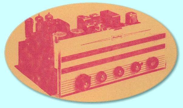
Stereo tuner-amplifier chassis. The Stereo 55 provided an output of 5 watts per channel from single-ended EL84's, and had vhf/mw bands. The volume controls for the two channels were on the same spindle but could be independently adjusted to control the balance. This set also included a ’stereo multiplex’ 4-pin socket which had input and output connections to fit a stereo decoder when these should become available. The source selector switch could choose VHF Stereo, VHF Mono, MW, Tape, Gram Mono, and Gram Stereo. (Gram meant disc pickup, of course!) The VHF Stereo setting would be used to connect the amplifiers to the multiplex socket and a decoder. The Stereo 55 was the first Armstrong set that was ‘stereo radio ready’, but of course actual stereo had to wait until the BBC started broadcasting, settled on a system, and a decoder was made available!

T4B

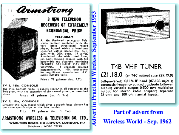
Stereo VHF tuner. (c1960). Full 87-108 MHz. AFC. Cathode follower output with variable output level 0-500mV. socket for Stereo multiplex decoder. 75 and 300 Ohm antenna inputs. Also available as T4C as chassis without a case.

Tele-Gram

Combined Television and 3-speed record player. (c1953) In modern terms this was quite an unusual combination. It was a full-size floorstanding TV, but with a lid on the top which could be opened to reveal a record player. The TV CRT was 14 inchs across. Walnut cabinet 35 inches high by 20 inches wide by 20 inches deep. 19 Valves. 5 Channel switchable selector. 10 inch loudspeaker.

TV 5

The TV 5 came in two versions. one had a 14 inch CRT and was identical to the Tele-Gram but omitted the record player. The other also omitted the record player but had a 17 inch CRT instead of the 14 one.


homeblue.gif - 1289 bytes
Click on the above logo to return to the home page.


Content and pages maintained by: Jim Lesurf
using HTMLEdit and TechWriter on a StrongARM powered RISCOS machine.