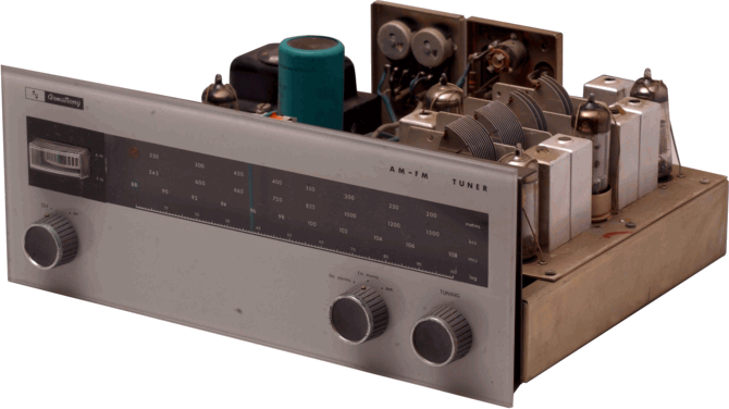
The Armstrong 223 AM/FM Tuner


223front.gif - 87Kb


Armstrong provided a choice of tuners and tuner-amplifiers in the 200 range - and in the associated 100 range. For the sake of example, here I've chosen to show and provide details on the 223 AM/FM tuner. The FM section of the FM-only tuner is the same as that used for the 223, and the tuner-amplifiers used the same tuner sections. Hence the details for the 223 cover the other units in the range. In fact, essentially the same tuner sections were also used in the 100 range units. These were similar to the 200 range, but had a single-ended output stage in their power amplifier. Today, a single-ended valve (tube) power amp is sometimes regarded as the ultimate in sophisticated audio. However in the early 1960's the single-ended option was provided as it was cheaper! At the time they were made, the 100 range was regarded as the baby brothers of the 200 range...

223toppic.gif - 143Kb


The above image shows a top view of the 223. Note that this example is monophonic and hence omits the optional stereo decoder. The main RF specifications of the 223 range receivers/tuners are listed in the table, below.

Specifications for 200 range tuners
Property AM Tuner FM Tuner
Coverage 500 - 1650 kHz 87 - 108 MHz
Sensitivity 7 microV for 20dB SNR 2 microV for 20dB Quieting
IF frequency 430 kHz 10.7 MHz
IF Bandwidth 2 kHz to 8 kHz (varies with signal level) 220 kHz (-6dB points)
IF rejection 60 dB 60 dB


The VHF/FM section has a coaxial 70 - 80 Ohm impedance input socket. The AM section provided an antenna connection and an earth connection. This was nominally for use with a long wire antenna of the kinds that were common during the period up to the early 1960's. The audio output performance of the VHF/FM section was essentially as quoted for the stereo decoder in terms of frequency response, etc. The AM performance was signal level dependent. Given a strong signal, the AM section was potentially capable of a much better audio performance than many modern AM receivers.

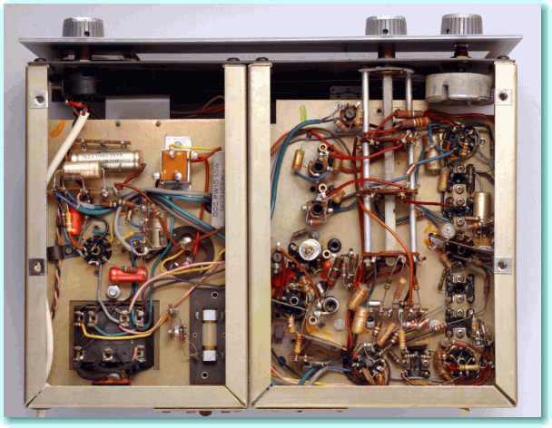
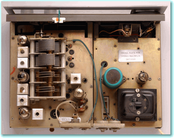
223botpic.gif - 169Kb


The above image shows the underside of the 223 chassis so you can see the general component layout.

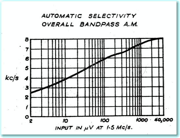
The Armstrong tuners often had novel technical features that provided unusually good performance. One example of this is illustrated by the graph shown lower down the page, taken from the user/service manual for the 223.

Today AM broadcasts from European broadcasters are tightly regulated, and no broadcaster is allowed to use a transmission bandwidth of more than 9kHz. As a result, modern medium-wave and long-wave broadcasts can only provide treble at frequencies up to just over 4 kHz. However decades ago, when the 200 range was produced, many broadcasters transmitted a wider range of frequencies. In those days FM radio in the UK was also fairly new, and many people tended to listen to AM as it provided a much wider choice due to all the foreign stations that could be picked up from outside the UK.

223bpgraph.gif - 96Kb


Back then, when listening to strong stations on AM, a better sound was often possible if you used a relatively wide IF bandwidth. However a wide bandwidth also meant that listening was more exposed to any background noise or interference. This probably didn't matter when the signal you were listening to was a strong one as it could then come through much louder than any unwanted noise or interference. But when the required station was very faint, a narrower IF bandwidth would help cut down on the amount of unwanted noise and interference.

For the above reason, the choice of IF bandwidth could be something of a compromise. A wider bandwidth could give more 'hi fi' results, but might mean some weaker stations were lost in noise and whistles. A narrow bandwidth would remove noise and whistles, but make the sound dull and lacking in treble.

The 200 range AM tuner dealt with this problem by the ingenious method of allowing the IF bandwidth to vary according to the signal strength. The result was to provide a wide bandwidth (and hence better sound) for strong stations, and a narrow bandwidth (and hence cut down on whistles and noise) with weak stations. The graph above shows how the bandwidth varies with the signal level.

The automatic variations of bandwidth with signal level were achieved by arranging for the bias level and hence the gain and anode impedances of the IF stages to vary with the signal level. This had the effect of changing the loading on the tuned circuits, thus obtaining this useful effect. In fact, Ted Rule discovered this effect by accident when experimenting with the design during development, and it was then incorporated into a number of the AM tuner designs that Armstrong produced.

223smallcd.gif - 63Kb


The image above shows a small version of the circuit diagram for the 200 (and 100) range tuners. If you wish to see a larger version of the diagram, you can do so by clicking on the image above.

As was common at the time, the design used the same gain stages in its IF section for both AM (medium wave) and FM (VHF FM) reception. Hence there are two tuned circuits in the anode (plate) connections for each valve - one for FM, one for AM.

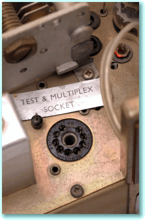
223mpxsocket.gif - 81Kb
When the 200 range was being developed FM stereo radio was still at the experimental stage in the UK. At first it was not even officially clear what system would be chosen, although the Zenith-GEC system was eventually selected. Around the time the units went on sale, a regular service was established, although a the time this was only from a few transmitters, initially at Wrotham (for London) and Dover. The stereo broadcasts were also only for a few hours per week, and restricted to what we now know as BBC Radio 3 for classical music and serious drama.

As a result of the initial uncertainty and the limited availability, the 200 range was made available in a mono form, but with a special socket and other provision made for the user to be able to add a suitable stereo decoder in due course. The picture to the left shows the socket that was provided on the chassis of the 223 for connection to a decoder.

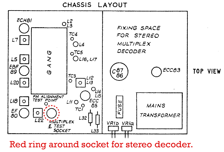
It is quite common for anyone who obtains an old 200 or 100 range tuner these days to find that it has this socket, with the original sticky label missing. As a result, it may look as if one of the valves is missing from the set as the socket looks a bit like a valve base. However the unit should be able to work perfectly well as a monophonic tuner even if nothing is plugged into this socket. The diagram below indicates the location of the MPX socket which will be vacant on a mono unit.

223TopLayout.gif - 19Kb


The plug-in decoder provided for the 200 and 100 ranges was the M5. The basic specifications for this are shown in the table below.

Specifications for M5 Stereo MPX decoder.
Frequency response 40 Hz - 15 kHz +/- 1 dB
Channel separation Better than 26dB at 1 kHz
Hum and Noise -60 dB
Filters 38 kHz, 40dB rejection


The tuner was already fitted with a mono/stereo switch and a green bezel for an indicator lamp. The M5 was built into a cadmium green steel case, and supplied with a cord and plug for connection to the 200/100 range unit from which it drew power. it was also supplied with a lamp and the relevant wiring which could be fitted behind the bezel. The stereo indicator lamp would then light up once the decoder was fitted and stereo was being received. The circuit used for the M5 MPX decoder was essentially the same as that employed for other Armstrong decoders such as the M12, M4, and M8. In each case the decoder was entirely solid-state and used germanium transistors and diodes. However the connection and power arrangements varied slightly from one type of decoder to another. The M12 was also in a steel case, and intended for use with the older Stereo 12, Stereo 55, T4, and ST3. Whereas the M4 and M8 were printed circuits boards that could be fitted into edge connectors in the 400 and 500 ranges, respectively.

The audio output level from the tuner could be adjusted using a pair of preset pots. Into a high impedance load these allowed any level from 0 - 2 Volts rms to be available from fully modulated signals. Into 600 Ohm loads the output would reduce to 250 mV rms with the presets turned up to maximum level.
back.gif - 204 bytes homeblue.gif - 1289 bytes

Colour photographs on this page
kindly provided by Loup.
Used by kind permission.

Content and pages maintained by: Jim Lesurf
using HTMLEdit and TechWriter on a StrongARM powered RISCOS machine.