The Armstrong 600 Series
Tuners and Receivers
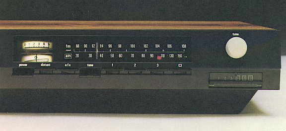
The above picture shows the 623 tuner. The tuner used for the 600 range was unusual in a number of ways. The most obvious of these was that the LW and MW bands were combined into one continuously tunable range.The AM tuner was also a double-conversion superheterodyne receiver with a first IF at around 3MHz. This gave unusually high selectivity to reduce interference. It also allowed the use of varactor diode (electronic) tuning. It was this technique which enabled the continuous LW/MW tuning. It also meant that electronic presets were available for MW and LW as well as VHF. All these features were novel at the time for a Hi-Fi system and came from the designer's (Ted Rule's) background as a radio amateur as well as his experience in earlier years with radio in the RAF.
| Coverage
| 87·5 - 108 MHz
| Frequency Response
| 30Hz - 14kHz -3dB
|
| Full Limiting
| 1 microV (mono)
| SNR 100 microV
| 65db (ref 75kHz dev.)
|
| IF
| 10·5MHz center
| 200kHz bw (-3dB points)
|
|
| Channel separation
| >40dB at 1 kHz
| THD (40kHz dev)
| <0·2%
|
Six tuning presets were provided. The preset channels were controlled by a set of six small multi-turn potentiometers. You can see these through the small transparent window which is under the main tuning knob shown near the right-hand end of the above picture. Armstrong were always concerned to make setting up and using their sets as pleasant and easy as possible. For this reason they provided the user with a small screwdriver to adjust these presets. When purchasing an FM-only tuner or receiver the six presets were all FM. On the FM/AM sets they were divided, three for FM, three for AM. Since the AM tuning was continuous each of the AM presets could be used for either MW or LW as the user chose.
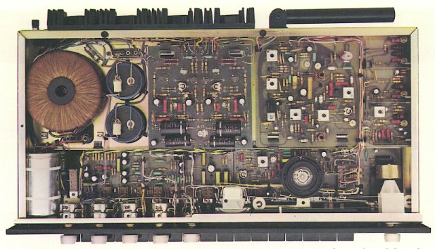
The above picture shows a view looking down into a 600 receiver with its wooden top removed. You can see the various circuit boards. The amplifier sections are to the left and the tuner to the right, with the VHF front end nearest the right-hand end of the box towards its back. The metal chassis you can see was elevated by the black plastic plinth. Some more circuits boards (including the power supply stabiliser and the stereo radio decoder) were mounted on the underside of the chassis and can't be seen in this top view.
Although modular like the 500 range, in the 600's the boards were placed horizontally, to allow for a lower profile. They were also hard-wired together with wired connections soldered onto pins fixed to the boards. The pins were flow-soldered onto the boards along with the other components. This construction method took a little longer to assemble than the 500's slot-in cards, and slightly slowed down board replacement when servicing. However it also removed any reliability problems due to poor edge-contacts. Hence the range was more durable that the 500's as well as more stylish.

Content and pages maintained by: Jim Lesurf
using HTMLEdit and TechWriter on a StrongARM powered RISCOS machine.