The Armstrong 600 Series
The 600 AM Tuner
Many of the tuners Armstrong produced used circuit designs that were unusual. The 600 range was an outstanding example of this. From the user's point of view this mostly just presented itself as a tuner that worked well and sounded good. However, for engineers and radio amateurs the circuits themselves were often very interesting to study. This page therefore looks at the 600's AM tuner and outlines how it functions.
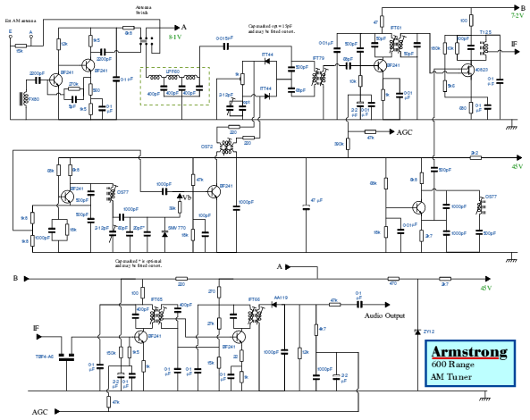
The above picture shows an over-view of the circuit diagram of the 600 range's AM tuner. This was probably one of the most unusual tuners ever to appear as part of a Hi-Fi system and had a number of quite rare feature that made it something special. From the user's viewpoint the main features were:
- The AM tuning combined the medium and long wave bands into one continuously tuneable band.
- There were AM presets as well as FM presets, all adjustable using small preset potentiometers.
- The level of apparent interference was often lower when listening to an AM station on the 600 than with more conventional tuners.
From the engineering viewpoint the 600 AM tuner had two special features which lead to the performance. The tuner used a double-conversion superheterodyne technique, with the first mixer up-converting the input to a higher frequency. The system enabled tuning to be made using just one single variable capacitance (using a single varactor diode) hence avoiding tracking problems. The ingenious design avoided many of the problems that beset conventional medium/long wave tuners. In particular, the receiver had unusually good image rejection.
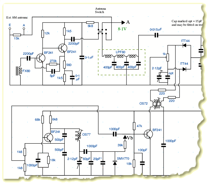
The above picture shows the front-end of the 600 am tuner. The signal could be provided using an external (wire) aerial or antenna and earth, the connections for which are shown top-left. Most users would, however, probably have used the Ferrite Rod antenna that was provided with the tuner. This is shown with the part number “FX80” in the above diagram. Although most modern AM tuners use a Ferrite Rod antenna, most employ the rod as part of a resonant circuit as a tuned antenna. The 600's Ferrite rod was untuned. It was followed by a two-stage broadband RF amplifier. (Using the pair of BF241 bipolar transistors shown top-left.)
Unlike most radios, the RF section of the 600's AM tuner was untuned. It picked up and amplified the entire medium wave and long wave bands. The entire frequency range up to about 2 MHz was then passed through a low-pass filter (shown as LPF60 in the above diagram). It then reached the first mixer. This used a balanced pair of ITT44 diodes.
The lower part of the above diagram shows the first Local Oscillator. This was arranged to oscillate at a frequency 3·1MHz above the frequency of the station to which the receiver was tuned. The oscillation frequency was controlled by the bias voltage, Vb, applied to a varactor diode (SMV770). This varactor was the only variable tuning element in the entire AM receiver! The desired output from the mixer therefore emerged at a first IF frequency of 3·1MHz. By choosing to up-convert the input to a frequency well above the medium wave band the tuner avoided many of the problems that beset conventional AM tuners. The low pass filter prevented any image frequencies from reaching the first mixer despite the RF amplifiers being untuned.
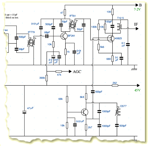
The 3·1MHz IF output from the first mixer was then passed on to the stages shown in the above diagram. The signal was now filtered by the resonant transformers show as IFT79 and IFT61. These, along with the BF241, amplified the desired signals at about 3·1MHz whilst filtering away other frequencies. The signal was then presented to a second mixer. This was a dual-gate MOSFET, the 40823, which was driven by a second Local Oscillator shown in the lower part of the above diagram. This second LO used another BF241 and was a fixed frequency oscillator, tuned to a frequency that was oscillating at 3100 - 455 kHz. As a result, the second mixer produced down-converted output at 455kHz. Hence the second IF was at the now-standard frequency of 455kHz.
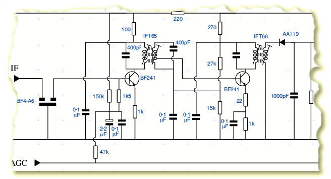
The output from the second mixer was then passed through a ceramic filter (TBF4-A6) and then through another pair of tuned transformers (IFT65 and IFT66) whilst being amplifier by another pair of BF241 transistors. These stages and filers were tuned to pass a band around 8kHz wide, centered upon 455kHz. The output was then AM demodulated using an AA119 diode. As well as providing the required demodulated signal (audio) the d.c. level from this diode was used to provide a control (AGC) voltage to adjust the gain of the IF amplifier stages and increase the working dynamic range.
The system is neat in that it gives good selectivity and avoids some of the image and harmonic problems of conventional MW/LW tuners, yet only requires one variable-tuned element. By using a varactor, the tuning can also be preset since it is voltage controlled. The only drawbacks are that the RF front end may be overloaded by unwanted high-power signals, and the front-end gain must therefore be kept low enough to avoid this. Hence the system does not give the untimate in distant or very local reception. However for most users it provides a reduction in apparent interference and hence means that some stations which come with “added whistles” on other tuners come through without interference on the 600.
The prototype for the 600 AM tuner had an oscillator which covered a much wider frequency range than production models. In principle, it is also possible to replace the LPF60 filter with a high-pass filter. Hence the same circuit could have been used as the basis of an “all waveband” short-wave radio combined with the medium and long wave bands.

Content and pages maintained by: Jim Lesurf
using HTMLEdit and TechWriter on a StrongARM powered RISCOS machine.


