|
Armstrong 626 renewal!
|
|
Ever since I first produced a website devoted to Armstrong Audio I’ve been contacted by many people who still use their amplifiers, tuners, etc on a daily basis. Most simply want to say how much they enjoy the Armstrong designs. This is pleasing because Armstrong did try to make durable, good looking, equipment that produced good sounds. But I don’t think any of us back then realised that so many people would still be happily using the 600 range well into the twenty-first century!
However some people ask if I service or mend Armstrong units. I’ve always had to explain that I don’t do repairs, etc. Instead I have happily suggested they try either London Sound or Armstrong HiFi and Video Servicing (AHVS). And I put their contact details on my website to help people find them.
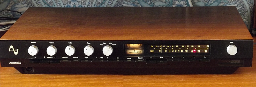
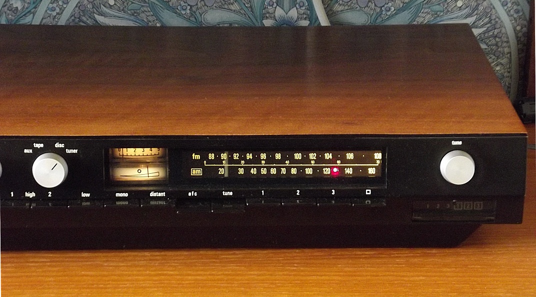
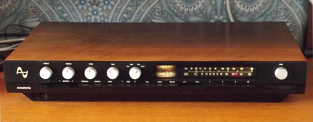
During much of this time I have used an Armstrong 626 receiver (i.e. tuner + amplifier) with a pair of Spendor LS3/5As as one of my audio systems. However in the last few years it had been showing signs of age. (Don’t we all!?) In particular, the meters and illumination had started to fail and it needed some TLC. Understandable in a unit that was made four decades ago.
In principle I could have tried fixing it for myself. But as I contemplated this it occurred to me that Mike Solomons of London Sound didn’t just repair Armstrong 600 range equipment he also offered to make some interesting modifications aimed at optimising the performance. So I decided to follow the same advice I’d given to others: I asked Mike to take a 626 and apply his skill to making it as good as possible.
In addition to repairs, Mike may replace components like old electrolytic capacitors that deteriorate. He can also perform two main modifications on the 600 range amplifier (which is, of course, used in the 625 and 626 receivers as well as the 621 amp). Here I’ll call them the “volume control modification” and the “power amp modification”.
From the user’s point of view, the most obvious effect of the volume control modification is that when they switch on the set the volume gradually “fades up” during the first few seconds. In itself this behaviour seems a nice match with the way that changing the input selection also “cross fades”. However its real purpose is to deal with a problem that tends to arise as the 600 range’s pre-amplifier section ages with use. This causes the volume control to start generating whooshing sounds or crackles when you alter the control in the first few seconds after turning it on.
To explain without getting bogged down in the details of the electronics: This behaviour arises because capacitors are used to prevent dc currents flowing though the volume control during normal use. However these capacitors have to charge up when the amplifier is switched on. So for a while a relatively large current flows though the control as the capacitors charge.
Any roughness in the contact between the mechanical parts in the volume control can then cause whoosh/crackle noises when the control is adjusted because this roughness generates noise from the steady current. And, of course, the potentiometers used for these controls are essentially mechanical devices that slide contacts along an internal resistor. So they tend to wear and become roughened with years of use.
Mike’s modification provides an alternative path for this charging current so that it doesn’t have to go though the volume control. It also suppresses the audio during the charging. Thus it tackles the noises and their cause. Instead of the unwanted noises you get a gentle fade up.
The power amplifier modifications improve the thermal stability of the power amplifier. This makes it possible to achieve improved, lower distortion, performance more consistently in use. The 600 range amplifier followed an early tendency in HiFi amps for the output devices to be on a heatsink that is mechanically separated from the board holding the smaller-signal devices that drive and control the output devices. The heatsinks are also quite small. In use, the various devices warm up to an extent that depends on how loud the music has been played recently. Ideally, the system should thermally “track”. i.e. the transistor circuits that drive and control the output devices should adjust to keep “in step” with the output devices. But in practice with all real world designs this thermal tracking won’t be perfect. The result is a tendency for the bias current though the output devices to vary in use. This can then mean the distortion levels, etc, also vary in use. The devices may also get hotter than necessary.
Mike’s thermal tracking modification therefore produces a number of useful results. In terms of performance the distortion will be reduced when playing music. You may also notice that the output devices are slightly warmer than before when you’ve only been playing music at low level, but not as hot as before when you’ve been playing loud music. The behaviour is more controlled and consistent.
Both these changes should improve the set’s performance in use. They don’t change the signal paths or the rest of the amplifier design. However they allow the original circuits to deliver their best possible performance.
|
Of course, if you own and like a 600 range this may present you with a dilemma – would you want the set kept ‘as made’ but working well, or would you want it modified in ways that Armstrong themselves never adopted? These days I suspect such equipment is beginning to be regarded as classic or vintage, and hence people might want the behaviour and internal arrangements to be as close to when the unit was first made and sold as possible. That’s something you’d have to make up your own mind about. You may want a set repaired and serviced, but not modified. I can only give my own view here...
I worked for Armstrong during the period when the 600 range was being made and sold. The company policy was “continuous development”. In practice this means the actual design in production was frequently altered in various ways to improve the performance. As a result, early sets tend to be less capable than later ones. The choice of active devices, sources of components, circuit details, etc, were routinely altered to steadily improve performance and reliability. Yet, externally, the sets looked the same, and were sold with the same printed specifications, etc, despite the improvements. Those who can read circuit diagrams can find two different versions of the 600 range diagrams which the company provided. However in reality small changes were made far more often. Too often for the printed sheets to keep up!
One of the changes I made when at the company was to choose a different type of volume potentiometer that used better materials. These were then much less liable to exhibit the noise problem. Early sets also included a thermal delay which limited the current inrush when the set was switched on. These had a tendency to fail (or emit smoke!) during the first few weeks of use. They were also expensive. So I changed the choice of diodes in the power supply and removed the delays entirely. I also changed the power amp transistors, etc.
The point of mentioning these details is that there isn’t actually one single circuit arrangement and set of components which constitutes a single ‘definitive’ 600 range. Unless you mean the very early first hundred or so - which weren’t as good as the last sets made. So my personal feeling is that Mike’s modifications make good sense if you like the 600 range and want a unit you have to work as well as possible.
In effect, if I’d remained with Armstrong, Mike’s modifications are ones I’d have adopted at the time! And when I discussed this with Mike he pointed out that he had spoken with Ron Sheppard - who also worked at Armstrong - and he’d wished the modifications had been made in production! So I was happy to ask for Mike to perform these on the 626 I sent to him.
Having contacted Mike and made the decision I spent ages packing up the 626. I was anxious about it being lost or damaged on the way to/from Mike. In the end I probably used up a reel of brown parcel tape before I convinced myself the cardboard box would survive. Having first wrapped the 626 in a plastic bag and multiple layers of bubble wrap, etc, inside the box. I still feared the package would be thrown on and off lorries by gorillas, and dumped in a pool of water somewhere along the way. This particular 626 (for the record, serial number 620546) means a lot to me for ‘historic’ reasons. It had previously belonged to Ted Rule who was the original designer. So I have a sentimental attachment to it in addition to liking the sound - and appearance! Even before sending it to Mike it was – to me – a special example.
Despite all that, the parcel reached Mike the morning after I sent it. Safe and sound. He then worked on it for a few days and we discussed what he was doing as he proceeded. He added the modifications, replaced components that needed changing, and got the meters, etc, working correctly again. Then did a general checkover and tweak to ensure optimum performance.
One interesting outcome for me was that he recommended leaving existing thermal delay circuits in place. This is because ones that have lasted for decades are probably going to go on working just fine. Until then my advice to people has been to remove/bypass the thermal delay and to fit better diodes as the rectifier bridge. But on reflection I realised I’d been conditioned by seeing the early failures decades ago, which have now, in practice, already weeded out the delays that really needed removal!
The set was then soak tested and returned to me. Mike did a better job of packing than I did. And again the carrier delivered it the day after it was uplifted. Despite my anxieties I was impressed that the couriers provided such quick service given that I live north of Edinburgh and Mike is in Harrow!
To my ears the modified set sounds superb. The meters, etc, now all work as new, and it looks great. The gradual ‘fade up’ after switch on actually seems like it could have been a period feature because the behaviour chimes with the ‘cross fade’ source selection fitting which was a hallmark of the 600 range amplifiers. The behaviour is quite unlike most modern equipment and has an elegance they seem to lack.
|
Externally, the only obvious changes are that the 626 looks newer because all the meters, etc, now work and look like new. At the back I can just see signs of a new application of heatsink compound between the output devices and heatsink. Thus confirming the work done to ensure improved thermal behaviour. Note that all the photos on this webpages are of the 626 after it was serviced and modified by Mike. Although I'm not a very good photographer, you can see it now looks like new. No sign of it being four decades old!
Because of the modifications the set now runs with a higher quiescent current and the output devices tend to get just warm to the touch. But the operating conditions don’t vary as much as they did in use, so the sound is more consistent. And listening to Radio 3 or 4 using the FM tuner demonstrates how much nicer these can sound via FM than via DAB. Ted Rule’s experience in the RAF and as a radio amateur shows in the care he applied to designing the 600 range’s tuner.
In conclusion my feeling is that I now have about the best 626 that Armstrong (almost!) ever made - although Mike feels some of the other 626s he has worked on are even better! There will, of course, be some sets which can’t really be completely restored. In particular, various special parts like the meters used by the tuner display are now hard to find in good condition. So you can’t expect a miracle every time. But in general I’d recommend anyone with a 600 range unit to consider trying Mike’s repairs/service/mods. Indeed, I’d recommend the mods as a definite improvement for the amplifier sections. I’ve always felt that a 600 range amp made a good match with the classic LS3/5A loudspeakers. Mike’s modifications have strengthened that feeling. I’m now very happily using the 626 with a pair of Spendor LS3/5A’s. An FM antenna, an Armstrong 626, plus a pair of LS3/5A’s. This is how the BBC mean Radio 3 to sound!
Jim Lesurf
7th Aug 2015