In my last two articles on loudspeaker cables I explored some of the theory and examined the implications for how various combinations of cable and speaker might behave. In particular, I looked at the way some choices might produce a difficult load for the amplifier. That was theory, but what about reality? To find out I decided to use an RF Vector Network Analyser (VNA) to measure the behaviour of some examples...
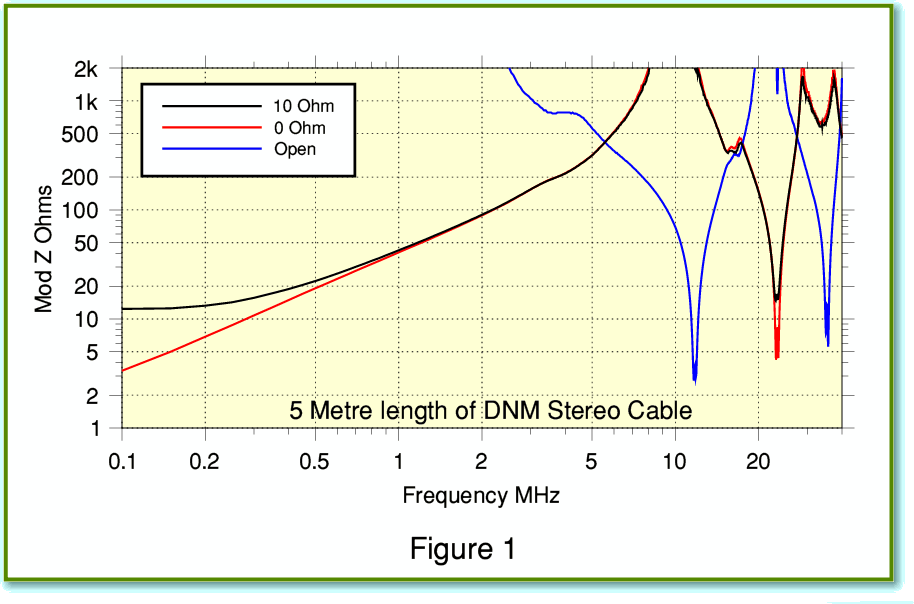
Figure 1 shows the results using a 5 metre length of the DNM Stereo cable whose theoretical behaviour I examined in the previous article on cables. The plots shows the magnitude of the impedance presented to the amplifier for three choices of load. One load is a 10 Ohm resistor. The others are a short circuit (0 Ohms) and leaving the loudspeaker end of the cable unconnected (‘open’ circuit) to mimic an infinitely high impedance. You can see that the general behaviour is similar to what I described in the previous article. The impedance presented to the amplifier varies with frequency and exhibits a series of peaks and dips. One particular point is that – as we might hope from the argument behind the design of the DNM cable – the dips don’t go down to extremely low impedance values. The minimum at an RF dip is around 3 Ohms in the region just above 10 MHz. So far as the amplifier is concerned this is much less demanding than if the dips had gone down to 1 Ohm or less.
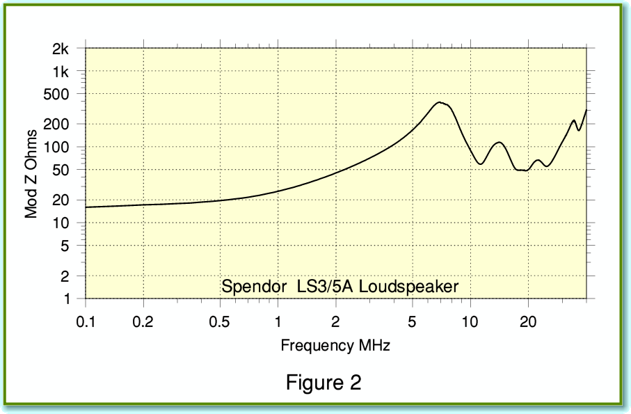
Now, in practice it is difficult to know what to expect when you connect a loudspeaker as no-one ever seems to take any interest in their impedance properties at these ultrasonic frequencies (SCAMP rule again, I fear[1]). Out of curiosity I did a measurement on a Spendor LS3/5A I have owned for some years. The results are shown in Figure 2. In this case the loudspeaker behaves like a load of around 50 - 500 Ohms or so over much of the relevant frequency range. But other loudspeakers may well give totally different results. For this reason I decided to use 0/10/infinite Ohms for my measurements. This covers the widest possible range, and 10 Ohms is similar to many speakers in the audio region.
In addition to the DNM I did measurements on a number of other cables. So far as possible I choose these to represent an assortment of geometries that differed from the DNM in various ways. This was to explore what factors were significant in practice. I also included some basic cables of the kind easily available from mail-order companies like Maplin, CPC, etc. As well as checking RF performance I measured the nominal properties with the results shown in Table 1.
| Cable
|
C'
pF/m
|
L'
microH/m
|
d.c. R'
milliOhm/m
|
Strand
Dia mm
|
Strands
|
velocity
% of c
|
Impedance
Ohms
|
| DNM Stereo Solid
|
13.8
|
1.2
|
104.30
|
0.65
|
1
|
82
|
282
|
| Maplin XS36
|
65.3
|
0.45
|
7.72
|
0.08
|
1050
|
62
|
83
|
| Maplin XR31 (VHF)
|
11.4
|
1.3
|
180.01
|
0.23
|
7
|
86
|
337
|
| Maplin XR72
|
67.3
|
0.55
|
16.16
|
0.20
|
79
|
55
|
90
|
| Maplin 4 way XS85
|
44.3
|
0.63
|
34.78
|
0.10
|
126
|
63
|
120
|
| Chord Carnival Classic
|
61.0
|
0.50
|
23.0
|
?
|
?
|
60
|
90
|
| Chord Silver Screen
|
81.0
|
0.42
|
26.0
|
?
|
?
|
57
|
72
|
| DNM wired as B3
|
31.1
|
0.52
|
52.0
|
0.65
|
2
|
83
|
130
|
| Townshend Isolda
|
2800
|
0.084
|
10.0
|
flat*
|
1
|
22
|
5.5
|
| Townshend Cabinet
|
65.0
|
0.30
|
51.0
|
0.55
|
3
|
75
|
68
|
(*Townshend Isolda uses flat strip conductors approx 15mm wide by 0.2mm thick.)
Table 1. Basic Measured Cable Parameters
The measured resistances are complete ‘loop’ values that include the resistance of both conductors. i.e. the values represent the total out-and-back resistance when using a cable. The number of strands given is for each conductor bundle. For most real cables the capacitance and inductance vary with frequency, so the values given above are averaged over a range up to about 1 MHz. The right-hand column of the table gives the nominal EM wave velocities implied by the measured capacitance and inductance. Although of interest, these velocities should not be taken literally for the reasons I explained in an earlier article. However the results show the same pattern as the those published by Martin Colloms[2]. There is a clear trend for the EM velocity to be lower for the higher capacitance cables. This may be a sign of an increase in capacitance being due to the presence of dielectric (insulator) materials which don’t alter the inductance by a balancing amount. For the loudspeaker cables (i.e. ignoring the XR31) the DNM has the highest nominal EM wave velocity
The Maplin XR31 is a 300 Ohm VHF antenna cable and isn’t intended for use with loudspeakers. I included it here as it is similar to the DNM in having a pair of widely-spaced conductors, although it uses 7 stands of copper per conductor bundle. It shares with the DNM a relatively high value for inductance, and low one for capacitance. The Chord Silver Screen is essentially a version of their Carnival Classic loudspeaker cable, but with an added screening. The screening is intended to reduce any interference or field coupling. The screen layer is not in electrical contact with the cable conductors used for the loudspeaker signals. The Townshend Isolda is an unconventional construction using a pair of flat strips of conductor, so can be expected to behave unlike more common geometries.
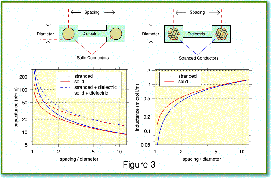
Figure 3 illustrates the way the values of capacitance and inductance per metre tend to vary with the relationship between the diameters of the conductors and the spacing between them when using standard ‘twin feed’ parallel wire arrangements. The solid lines on the capacitance graph assume any dielectric effects are so small that the EM wave travels at the speed of light. The broken lines assume the dielectric used slows down the wave to just 80% of the speed of light. Two arrangements are shown. One assumes the use of solid conductors, the other assumes bundles of many tiny conductors. In each case the conductors/bundles have a circular cross-section.[3] The strands in each bundle are assumed to be individually insulated and arranged so that the current is uniformly distributed amongst them. This helps prevent the ‘skin effect’ which tends to cause the series resistance (and inductance) to rise with frequency – often regarded as something to avoid. Hence the preference by various people for multistranded conductors. A choice that runs contrary to the DNM approach which exploits skin effect (more accurately called ‘internal impedance’) to help control RF behaviour.
Maplin XS85 is similar to the DNM Stereo cable in having four conductor bundles which can be used for bi-wiring or running Left and Right channels in parallel. But the XS85 uses around 126 strands per conductor bundle whereas the DNM uses a single strand for each. Maplin XR72 is fairly typical of modest cost general-purpose loudspeaker cable. Maplin XS36 uses fairly fat bundles of over 1000 thin strands of wire with the bundles closely spaced. So the XS36 represents a loudspeaker cable which – for conventional ‘twin feed’ arrangements – differs most from the DNM.
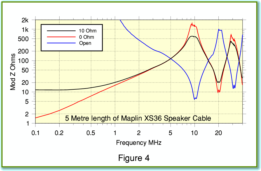
Figure 4 shows the RF impedance results for the Maplin XS36 multistranded cable. If you compare these measured results with the theoretical ones in my last cable article the striking feature is that the impedance never actually drops very low in the region above 1MHz! At first sight this seems odd. We might expect a cable using many tiny strands to have a low series impedance at RF due to the multistanding. There are various possible reasons for this discrepancy. For example, there might be other losses – e.g. due to a poor dielectric being used as an insulator. However the actual cause may be simpler. Despite using over a thousand tiny strands per conductor bundle, the construction of the Maplin XS36 (and some other similar cables) behaves much like one single, thick, conductor. This means the series resistance rises with frequency, and tends to reduce the swings in impedance.
The key point here is that the use of many tiny conductors in a bundle to suppress skin effect depends on the strands all being individually insulated. Otherwise, if they are all in electrical contact, currents can flow from one strand to another in the bundle. Yet many conventional mulitstranded cables like the XS36 don’t use individually insulated strands! The result is that – even if the strands are all neatly braided or interwoven – the currents tend to transfer from wire to wire and can manage to stay at the outside of the bundle. Just as if the bundle were one fat conductor, although admitted now one that has a fairly ‘rough’ surface due to the stranding. Indeed, in this situation the surface roughness may well mean the series resistance at high frequencies is greater than if we’d chosen a single, smooth surfaced, conductor of the same overall diameter. Hence the alarming dips predicted by simply theory may not always materialise in practice. The irony here is that people in audio tend to regard skin effect as ‘bad’. But – consistent with DNM’s approach – it may actually be useful in cases like the Maplin XS36 to avoid awkward amplifier loading in the ultrasonic/RF region.
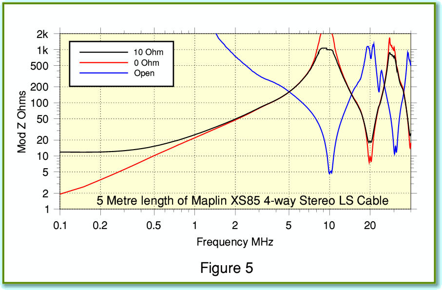
Figure 5 shows the measured results for the Maplin XS85 stereo cable. Once again we can see that, despite being multistranded, the impedance above 1 MHz never dips down below a modest level. The results we get will, of course, vary depending on both the choice of cable, and the cable lengths as well as with the choice of loudspeaker. Some combinations might show much more alarming RF impedance dips than I have measured. But in general it looks like inexpensive multistranded conductors don’t represent a serious RF loading problem. The result being that skin effect may work to our advantage without our knowing, despite its reputation as a villain. Oddly, this might mean that cables like the Maplin examples which don’t normally feature on the radar of audiophiles might actually be a better bet in some cases than more fancy cables which use constructions that combat skin effect!
Having looked at the issue of solid core versus multistranding, the other interesting feature of the DNM Stereo cable and the Maplin XS85 is the provision of four conductors running in parallel. So let’s now turn our attention to that... The above measurements all used an adjacent pair of conductors as intended by the makers for non-biwired use. The other conductors were left unconnected to anything at either end. But we could choose to use them in a variety of ways.
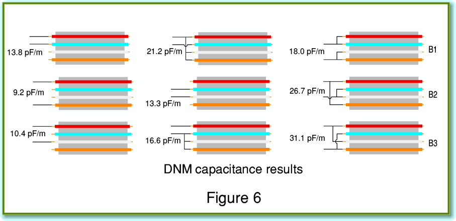
Figure 6 shows various ways in which we could connect to a 4 conductor cable. The example shown at the top-left represents the expected arrangement where we use one adjacent pair (red and blue in this case) as the wires to link an amplifier to a speaker. The orange and white wires might then be used for the other stereo channel. The measured capacitance for this was 13·8 pF/m. For biwiring we might use one of the arrangements I have labelled B1-B3. Note that each of these has a different shunt capacitance value. Less obvious until pointed out is that the arrangements also have different inductive couplings between the various pairs of conductors.
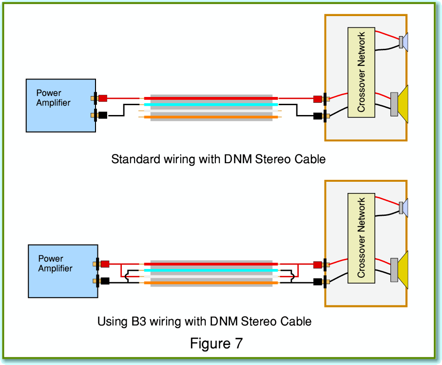
However, if we wish, we can use the wires in parallel pairs to connect to a load. Figure 7 illustrates an example of this. The arrangement shown at the top of Figure 7 shows the conventional use of a pair of the conductors to link one channel amplifier to one loudspeaker (without biwiring). The arrangement shown at the bottom of Figure 7 shows the ‘B3’ wiring which employs all four conductors. In this case the paired wires are joined at both amplifier and loudspeaker. The arrangement would halve the series resistance of the cabling, and the capacitance would rise as indicated in Figure 6. The increase in capacitance is balanced by a fall in the series inductance. Values for the DNM stereo cable used in this way are included in Table 1.
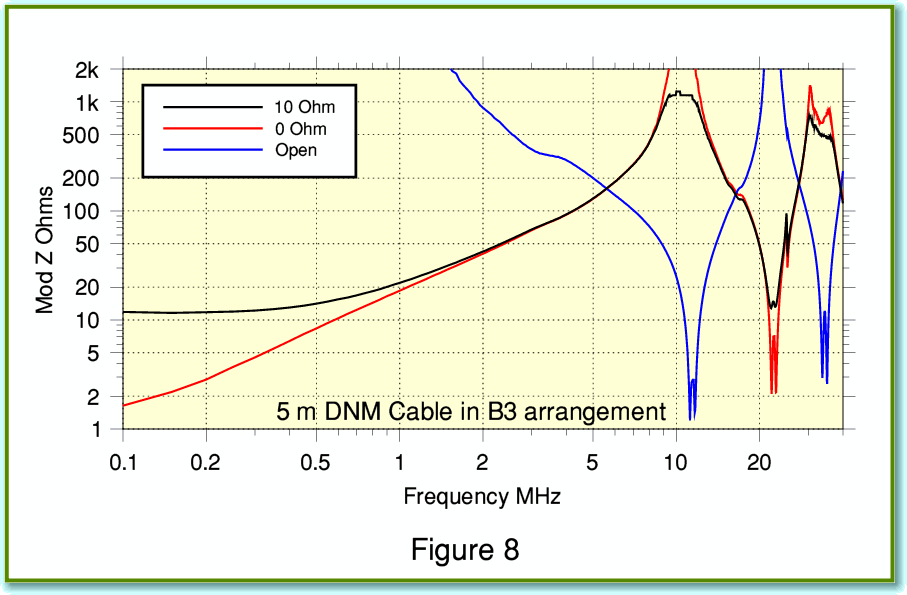
The main advantage of lower series resistance and inductance is to reduce any variations in audio frequency response caused by interactions between the cable and loudspeaker impedances. The drawback is illustrated in Figure 8 which shows the RF impedance behaviour using the DNM B3 arrangement. You can see that the minimum impedance levels are now well below 2 Ohms at just over 10 MHz. This is a much more severe dip than we got using the DNM cable as intended. Comparing Figures 1 and 8 supports the DNM argument that the mix of properties of the DNM cables provides a sensible trade-off to minimise RF loading upsetting the power amplifier. But of course, this does mean using the cable as DNM specify!
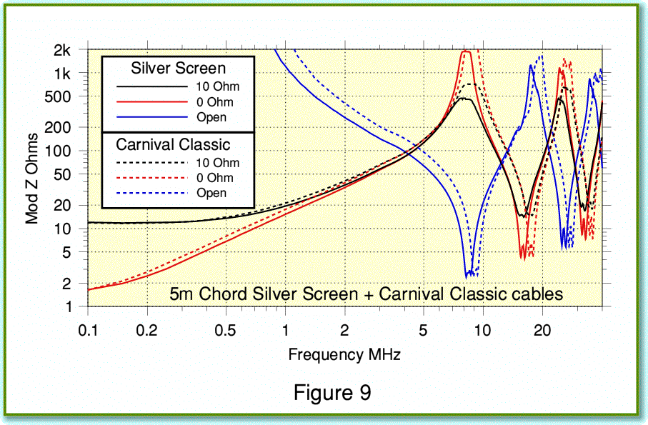
Figure 9 shows the results I obtained when using the Chord cables. To make the differences netween them more obvious I’ve plotted both types of Chord loudspeaker cable on the same graph. One interesting feature is that the frequencies at which the peaks and dips in impedance occur tend to be at slightly lower frequency than with the other cables I have illustrated so far. This is a sign that the product of the inductance and capacitance per meter of the Chord cables is larger. The effect is to slow down the velocity of propagation of the EM waves conveyed by the cable. The screening enhances this behaviour which may indicate that the dielectric used as insulator is causing the capacitance to rise by a larger amount that the inductance falls. The minimum impedance values shown in the dips indicate that the Chord cables maintain low series resistance at high frequencies, so exhibits lower skin effects than most of the other cables I have examined in this article.
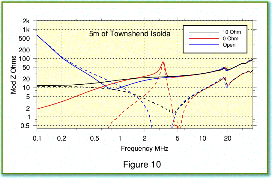
Finally, Figure 10 shows the results I measured using a 5 metre length of Max Townshend Isolda loudspeaker cable. The solid lines shown the behaviour including the inductors which are normally supplied as part of the cable. The broken lines show the results without these additional components.
The behaviour of the Isolda cable is very different from the other types I have measured. This is a consequence of its unusual geometry. Note that I extended downwards the vertical scale in Figure 10 as – used without the standard Townshend inductor network – the measured impedances without the inductors drop at some frequencies to values well below 1 Ohm! From the conventional point of view, the big advantage of the Isolda cable is that is exhibits exceptionally low series inductance, combined with low resistance. If your concern is to obtain an audio signal waveform at the loudspeaker terminals which is as close as possible to that at the amplifier output then the Isolda looks like a good choice. However as with the DNM cables, some specific arguments are put forwards for the use of the cable by its makers. I hope to investigate this in my concluding article in this series on loudspeaker cables, and draw some general conclusions from all the measured results.
Jim Lesurf
14th Sep 2008
2600 Words
[1] SCAMP. Jim Lesurf Hi Fi News pp 100-102 May 2007
[2] The Cable Survey: Part 2 Speaker Wires. M. Colloms Hi Fi News pp 50-53 July 1990
[3] The Isolda cable is more like a long, thin parallel-plate capacitor.
