Digital systems like Compact Disc work by converting the audio waveforms into series of binary numbers. The results are then stored on an Audio CD as a sequence of 16-bit integer values. This means there are only 216 = 65,536 possible values to choose from for any individual sample. Normally, 0dBFS (Full Scale) is defined as what we get from using the largest values. We then generally assume that we can record levels right up to this limit, but cannot go above it as there would be no way to represent these ‘out of range’ levels. The system seems to have a ‘brick wall’ limit in terms of loudness
In a previous article[1] I showed that various audio CDs are seriously level compressed and clipped. In some cases, the CD contains thousands of instances of sample values that are as large as CD can represent, and sometimes these turn up in ‘runs’ of successive maximum-value samples. This seems bad enough as the results are then seriously distorted. But is it really that simple? Or can we go ‘over the top’?...
In terms of Information Theory we should determine the waveforms which – when limited to the Nyquist limited bandwidth (22.05kHz for CD Audio) – the sample values define. Filtering to the Nyquist bandwidth is an important part of both the recording and replay processes. But most people seem not to have realised that this implies the result can potentially produce waveforms that extend to levels greater than the maximum sample values. A paper on this topic was presented at a recent Audio Engineering Society Convention[2]. However, here I want to take a slightly different approach as I think the results are more revealing.
Lets consider a digital recording system as it might be described in an engineering or information theory textbook. Initially I’ll just consider one channel and ignore the need for two or more sets of numbers if we want stereo, surround sound, etc. I’ll also assume we’re recording/replaying audio CDs.
It is common practice for the main part of the filtering – both during recording and replay – to be carried out using digital filters. So for the sake of my numerical models I’ll assume this is done using digital filter processes at x8 the CD sample rate. (In practice, much higher oversample rates may be employed, but that doesn’t change the arguments and conclusions that follow.) Traditionally, engineers have also tended to prefer using digital filters which are described as time-symmetric FIR (Finite Impulse Response) designs. The main reason for this is that such filters can avoid delaying components in the audio waveform by amounts that depend on their frequency, and we can get a very flat response inside the audio band. These filters are also easy to design.
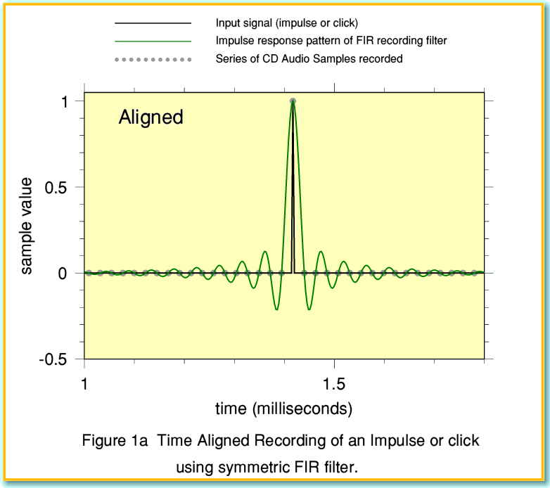
We can see the effect of the filtering by recording or replaying an ‘impulse’. This means an input which is essentially a very brief ‘click’ – i.e. a signal that is zero at every moment except for one instant. The FIR filter used during the recording process removes any signal energy at or above 22.05kHz. Typical results in terms of the samples recorded are shown in Figure 1. For the sake of clarity I’ve scaled all the values so that the maximum possible sample amplitude corresponds to 1.0. i.e. This means the samples all fit in the range from -1.0 to +1.0.
Figure 1a represents a click or impulse being recorded as a series of sample values. In this example the click happened to occur at one of the sampled instant. In effect, the click is time aligned with the samples. The result is that only one sample value is non-zero – the one at the instant the click occurred. In such a case the effect of the recording filter on impulses isn’t obvious from the recorded values which are represented by the grey blobs.
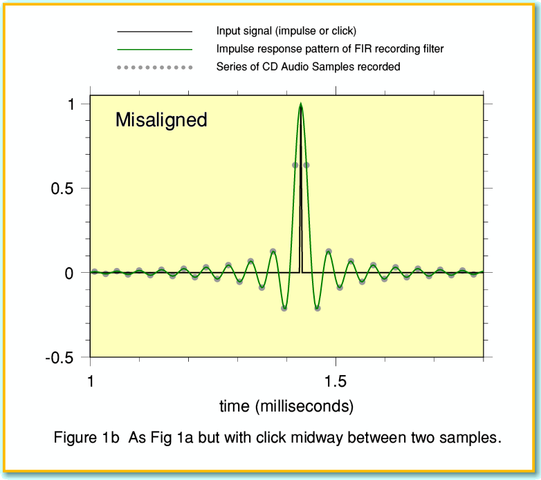
However if the click didn’t occur precisely at one of the instants at which sample values were recorded then the filter’s behaviour becomes apparent. This is illustrated by the graph shown in Figure 1b. In this case I’ve arranged for the click to appear mid-way between two sampled instants. In both graphs the green line shows what we call the Impulse Response of the filter used for the recording process. This determines the pattern of the sample values we’d get from a click. In the misaligned case none of the samples around the click are of zero value. In particular, note that the two samples closest to the click are on the ‘shoulders’ of the pattern. As a result, their values are well below the peak level of the filtered waveform represented by the series of sample values.
These patterns arise because the recorded signal must have a finite bandwidth. Various articles over the years have discussed the ‘ringing’ which shows up in the pattern around the click[3]. There has been a lot of debate about if this is bad news or not. In particular, people have considered this effect in the filtering used by the player to reconstruct the required waveforms from the sampled data. Here, however, I am interested in the implications of the misaligned pattern not actually having a sample up at the peak of the waveform.
As I’ve discussed in some earlier articles, one of the curses of modern audio is the tendency for people who make recordings and broadcasts to wind up the signal level as loud as they can. This means that once a recording was made, it would be all too probable that someone would decide that it could be ‘improved’ (i.e. made louder!) by simply scaling up all the sample values until the largest ones are at full belt! So let’s now investigate what that would mean when you come to replay the results...
Figure 2 shows the kinds of results we might get if a recording had been made of an impulse that was misaligned, and the recording producers/engineers had then blythly ‘normalised’ the recording so that the largest samples reach the maximum possible values. As in Figures 1a and 1b, the grey blobs represent the sample values on the CD. The green line now shows what a player should produce if it used a time symmetric FIR filter, and the player was built so that 0dBFS corresponded to an output of 2 Volts peak to peak. i.e. the maximum positive and negative sample values should output +1V and -1V respectively. The result shown is then required by the relevant parts of Information Theory and reconstructs the waveform keeping within the bandwidth limitations for CD. However, as you can see, the peak of the waveform is now well above the +1 V level. In fact it reaches a level about 4dB above the power of the largest individual sample values we can represent on an audio CD! The good news is that – if the player acts in this ideal way – the resulting waveform need not be clipped, and can have the intended shape when the recording is played.
Alas, if the designer of the CD player wasn’t expecting it to have to handle signals that reach well above 0dBFS, then the electronics in the player may not be able to cope. For example, if the filtering in the player is in the digital domain then its calculations might overflow and simply not be able to generate values above 0dBFS. The result then might be snipped flat as shown by the orange line between the two max-level samples. The result will be distortion.
I should confess that I chose the above example of a misaligned impulse deliberately as a ‘worst case’. To do this I used an area of Communications Theory which involves what engineers call Matched Filters. I won’t go into details here, but the maths for this allows us to predict which signal waveforms will tend to give the maximum response with a given type of filter. So I used that method to produce the largest excursions out of range for the chosen filters. This turned out to be around 4dBFS in the case I’m using as an example.
In practice it’s unlikely that anyone is carefully recording misaligned impulse clicks, scaling them, and selling the results as music. But it is common for CDs to be level compressed and clipped. So problems may well arise when playing such thoughtlessly produced CDs. The results will vary from one CD to another, depending on the details of what data has been recorded. For the sake of example I decided to examine one of the CDs which I’d previously discovered has significant amounts of clipping.
Figure 3 shows some results for a section taken from the Mercury Living Presence 1812 Overture CD I’ve used before as an example of gross clipping. The small grey blobs represent the sample values. The red and blue lines show the left and right channel audio waveforms we get if we employ the same FIR reconstruction filter as above, and assume the player is designed to cover a range from +1 to -1 Volts for 0dBFS. The times shown indicate the time from the start of a 50ms section of the track chosen for the example.
To make the situation clearer, Figure 4 shows two sections from the same waveforms, but “zoomed in” to display them in detail. The results show excursions reaching peaks up to +2dBFS. In fact, with this particular CD the waveforms should cause the player to exceed 0dBFS on many occasions. This example confirms that waveforms requiring large out of range excursions will occur when some real CDs are played. So this isn’t just a theoretical problem!
Alas, assessing the practical impact of the problem is difficult for various reasons. The first and most obvious being that we really need to analyse many CDs to see how often problems arise in practice. It was depressingly easy to find the example I’ve used here. But I don’t know how typical that may be of the many thousands of CDs on sale. Here I can simply show another example, taken from a relatively recent ‘Queen’ CD set.
This was a special issue available on both CD and LP called “Queen Rocks”. You might think that both the LP and CD would have been mastered with care and attention. But the above excerpt clearly shows that the CD version has obvious periods of flat-top clipping, and regions where the signal in between samples can be expected to be well over the 0dBFS level.
The results also depend on the details of the reconstruction filtering. Some ‘audiophile’ players avoid using the standard FIR designs of filter, and this has been claimed to be a reason for them producing better sounding results. The need for the reconstruction filter to occasionally create out of range levels raises an interesting possibility. People have often speculated (or claimed) that novel forms of CD player reconstruction filter ‘sound better’ because they avoid ringing effects. However, might be it the case that the real reason a change in sound quality is noticed is that the form of the filter chosen alters the results when clipped or excessively loud CDs are played? In particular, when the CD data indicates a waveform that extends well above 0dBFS? Might it also be the case that two players which behave indistinguishably when reproducing lower level signals can give audibly different results when called upon the reproduce waveforms above 0dBFS?
At present it is hard to answer this question with any confidence as we lack the necessary date on the details of what kinds of out of range excursions might appear, and how often, on typical audio CDs. However previous work on clipping indicated that a worryingly large number of rock and pop music CDs show clipping, whereas it seems rare for CDs of classical music or jazz to do so. Hence the type of CD chosen for listening tests may be a factor here.
What any specific player/disc combination may do remains intriguing open question. With this in mind, I discussed the problem with Keith Howard. He decided to investigate and test some players to see what results they produced. Do they produce the kinds of waveforms which the simple models say they should? Or do they distort and alter the results in various ways? Does the filtering significantly alter the results?
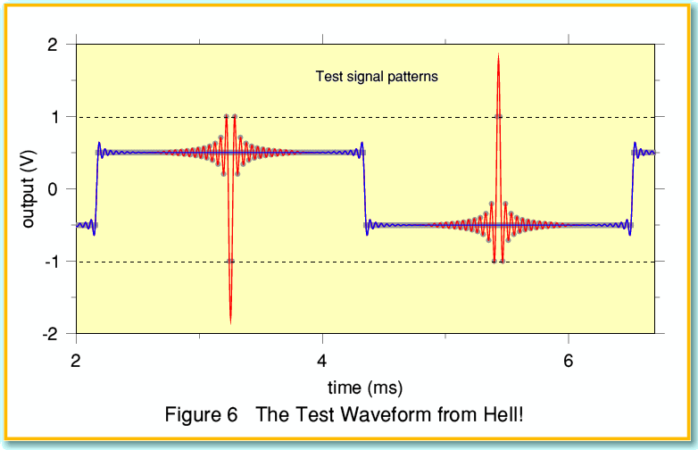
The ability of sampled data to imply output levels above 0dBFS when used to reconstruct an analogue waveform leads to two other interesting questions. What is the largest possible peak level above 0dBFS which might then occur? And what waveform and series of samples produces this result? It is quite hard to answer these questions as the answer will depend on the details of the reconstruction filtering in the player. But I managed to devise what looks like a fiendish ‘worst case’ result which I decided to call, “The Waveform from Hell”! This is shown in the figure below.
This example is based on the impulse function of the commonly used time-symmetric reconstruction filters and is tailored to be demanding for such replay systems. The size of the impulse patterns has been maximised by arranging for the samples to cover the entire range allowed. This means the baseline of each pulse has to be offset away from zero. So to balance this, there are spikes of alternating sign, thus cancelling out any dc level. Two waveforms are shown. One (blue) is simply a bandwidth limited squarewave showing the alternating spike offset.The other (red) has the demanding spikes added. These now reach up to over +5dBFS. Since all the sample values are in the permitted range, a player should – in theory – be able to produce the waveforms displayed when the samples were played. We could then be confident that the player could play essentially any CD without adding unnecessary distortion. But is there a CD player that could cope?...
It is clear from the above that – in principle – the player should be able to cope with providing output levels up to 5dB above 0dBFS. Although in practice being able to cope with a more modest 3dB would probably be fine for nearly all CDs of real-world recordings - even those which are grossly clipped and damaged by poor mastering. Ideally, non of these problems need arise in practice since the people creating audio CDs of music should be aware of this problem, and simply keep down the recorded levels so at to avoid the reconstructed waveforms needing to go ‘over the top’. Alas, as the existence of heavily clipped CDs shows only too well, their main concern often is, “How loud can we make it?” And the player may then have to cope with the resulting problems...
[1] Clipping on CD. Jim Lesurf Hi Fi News Dec 2006 p22
[2] 0dBFS+ Levels in Digital Mastering. Neilsen and Lund 109th AES Convention paper.
[3] Ringing Enforcement. Keith Howard Hi Fi News Jan 2002 p72


