Radford Electronics remain well regarded for their valve power amplifiers. This is because the amplifiers gained a well-justified reputation for outstanding performance. This webpage provides examples of the circuit diagrams of their STA (STereo Amplifier) and MA (Mono Amplifier) power amps, and outlines the development in the designs. I’ve omitted all power or voltage ratings as the circuits are not displayed for constructional purposes, but to enable study of the circuit topologies used. I’ve also omitted details of the transformers which would be vital to the actual performance. The details of the physical wiring arrangements and the ground paths would also affect performance.
The original MA/STA amplifiers appeared at the start of the 1960s The STA12 was reviewed in the March 1961 issue of ‘Hi Fi News’ magazine.
Click here for a larger version of the circuit diagram.
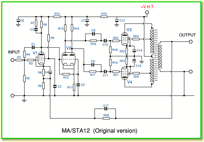
The above shows a circuit diagram of the MA/STA12 (the stereo amp simply used two of the mono amplifiers with an uprated power supply.) The version shown is based on the circuit described in Hood’s Valve and Transistor Amplifiers. N.B. The diagram in Hood has some obvious errors which I have corrected. However they may be more subtle errors which I have missed in the above, and also in the values below!
Component List for original MA/STA amplifiers
| R1 = 47k
|
R2 = 220k
|
R3 = 4k7
|
R4 = 1M2
|
R5 = 390k
|
R6 = 100k
|
R7 = 4k7
|
R8 = 2k2
|
| R9 = 100
|
R10 = 1M
|
R11 = 82k
|
R12 = 270k
|
R13 = 180k
|
R14 = 185k
|
R15 = 15k
|
R16 = 1M
|
| R17 = 1M
|
R18 = 470k
|
R19 = 470k
|
R20 =4k7
|
R21 = 2k2
|
R22 = 470
|
R23 = 470
|
R24 = 1k
|
| R25 = 1k
|
R28 = 2k7
|
C1 = 10n
|
C2 = 0.05
|
C3 = 1n
|
C4 = 50
|
C5 = 0.25
|
C6 = 8
|
C7 = 8
|
C8 = 10n
|
C9 = 10n
|
C10 = 0.1
|
C11 = 0.1
|
C12 = 20
|
C14 = 50
|
C15 = 50
|
| C17 = 1n
|
V1 = EF86
|
V2 = ECC83
|
V3 = EL34
|
V4 = EL34
|
|
|
|
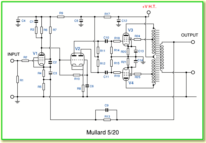
In practice, as pointed out by George Tillett in the HFN review, the design was a tweaked version of the widely used Mullard 5/20. For the purpose of comparison the diagram of the 5/20 is shown below.
Click here for a larger version of the Circuit Diagram.
Component List for Mullard 5/20
| R1 = 1M
|
R2 = 4k7
|
R3 = 4k7
|
R4 = 2k2
|
R5 = 100
|
R6 = 100k
|
R7 = 390k
|
| R8 = 82k
|
R9 = 270k
|
R10 = 1M
|
R11 = 180k
|
R12 = 180k
|
R13 = *
|
R14 = 470k
|
| R15 = 470k
|
R17 = 15k
|
R18 = 2k2
|
R19 = 2k2
|
R20 = 470
|
R21 = 470
|
R24 = 1k
|
| R25 = 1k
|
C1 = 47p
|
C2 = 0.05
|
C3 = 50
|
C4 = 8
|
C5 = 8
|
C6 = 0.25
|
| C9 = *
|
C10 = 0.5
|
C11 = 0.5
|
C12 = 8
|
C13 = 50
|
C14 = 50
|
|
The values marked as * should be chosen according to the load.
- 4 Ohm load R13 = 3k9, C9 = 470p
- 8 Ohm load R13 = 5k6, C9 = 330p
- 16 Ohm load R13 = 8k2, C9 = 220p
The improvements made by Arthur Radford were mainly based on his ability to produce superb output transformers. However if you compare the above designs you can see some ‘tweaks’ which were applied to the 5/20 circuit to help the MA/STA deliver improved performance. The most significant of these are in two places.
- The components labelled as C1 and R4 in the original MA/STA design apply some local anode-grid feedback to the first gain device, V1. Although this reduces the open loop gain it tends to flatten the frequency and phase response. It also reduces the output impedance of the first stage which means the second stage is less affected by its own Miller capacitance.
- The components C8, R16, C9, R17 act as gain/phase correction networks in between V2 and the output valves.
Given the good output transformers, the above changes meant that global feedback could improve the performance without risk of instability. Thus the design could achieve outstanding performance.
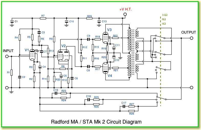
Although the original MA/STA design was well received, Arthur Radford felt he could do better. He therefore worked with Arthur Bailey and within a year they developed the ‘Mk2’ version.
Click here for a larger version of the Circuit Diagram.
Component List for MA15 Mk 2
| R1 = 100k
|
R2 = 100
|
R3 = 2k2
|
R4 = 330k
|
R5 = 100k
|
R6 = 2k7
|
R7 = 220k
|
| R8 = 1M
|
R9 = 33k
|
R10 = 8k2
|
R11 = 33k
|
R12 = 39k
|
R13 = 1M
|
R14 = 1M
|
| R15 = 470k
|
R16 = 470k
|
R17 = 2k2
|
R18 = 2k2
|
R19 = 390
|
R20 = 390
|
R21 = 1k
|
| R22 = 1k
|
R23 = 560
|
R24 = 3k9
|
R25 = 390
|
R26 = 2k7
|
R27 = 270
|
R28 = 1k8
|
| R29 = 8k2
|
R32 = 68k
|
C1 = 8
|
C2 = 0.1
|
C3 = 500p
|
C4 = 50
|
C5 = 2
|
C6 = 1
|
C7 = 4n7
|
C8 = 0.1
|
C9 = 0.1
|
C10 = 16
|
C11 = 50
|
C12 = 50
|
C13 = 20
|
C15 = 270p
|
C16 = 1n
|
C17 = 340p
|
V1 = EF86
|
V2 = 6U8*
|
V3 = EL34
|
| V4 = EL34
|
|
|
|
|
|
|
* V2 may also be an ECF82
The above lists the values as given for the Hi Fi News constructional version of the MA15. This appeared in a series of article from June to September 1962. Note that R32 was an addition made in the last article, so isn’t shown in the diagram in the June 1962 issue. To change the design into an MA25 Mk2 the following changes were made.
Component List changes specified in HFN for MA25 Mk2
| R19 = 470
|
R20 = 470
|
C3 = 680p
|
C13 = 40
|
V3 = KT88
|
V4 = KT88
|
The changes that distinguish the Mk2 from the original versions are in two areas
- A better output transformer.
- The phase splitter stage (V2) uses a pentode-triode instead of a double-triode.
The change to a pentode-triode was a development by Arthur Bailey and has a dramatic effect on the open loop gain of the amplifier. In effect, although the double-triode only had a flat gain bandwidth of around 15 kHz, the pentode-triode extended this to above 150kHz. As with the previous design, this flattening of the open loop response in terms of amplitude and phase made the amplifier inherently better, and allowed global feedback to provide further improvements without the amplifier oscillating on some loudspeaker loads.


