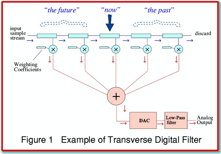
Low Pass filtering and the Transverse Digital Filter
The digital reconstruction or resampling filters employed in most digital sound processing systems tend to be based on methods equivalent to what is usually called a Transverse Digital Filter (TDF). This has some curious properties that we can understand using Figure 1. The TDF contains a series of memory locations in which it can temporarily store incoming digital sample values. These are arranged to hold data a little like the way a row of people might sit on a park bench. As each ‘new’ value appears it shoves onto one end of the bench (line of storage locations) and the earlier values are all pushed along one place to make room for the newcomer. Once the bench (called a shift register) is full, each time a new value arrives and shoves onto one end, an ‘old’ value is pushed off the other end and is discarded.
Each time the filter has to calculate an output (i.e. filtered) value that is required for a given instant it does so by looking at all the input values for instants around that time. The process consists of multiplying each input value by an appropriate, pre-defined, coefficient value. This series of coefficient values defines the filtering action of the process. As new input values regularly arrive the process is repeated to work out fresh output values. For the sake of clarity, in Figure 1 above I’ve just shown five memory locations in the shift register as the blue boxes along the top of the diagram. Most practical systems have many more registers than this and hence can include contributions from many more input values at any given time than shown in the diagram. I’ve also ignored various other details of most real systems in order to simplify this explanation!
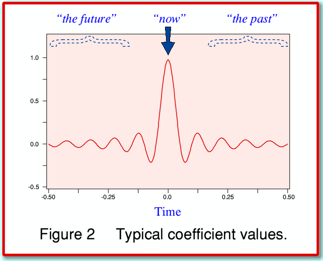
Many of the existing systems used in CD players. etc, have a “Time Symmetric” set of coefficient values. For the sake of the examples in the ‘Ringing in the Ears’ pages I’ve chosen the most basic time symmetric behaviour described in the textbooks and used the pattern illustrated in Figure 2. This is based up what is called the Sinc function low-pass filter. This shows the classic, 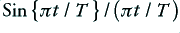 , pattern for a chosen low-pass cut-off frequency of 10 cycles per unit time.
The time symmetry means that for any output instant we have to take into account both ‘past’ and ‘future’ values. i.e. the system has to have some information about what pattern details are approaching as well as those that have just passed by. We do this by treating the values in the middle of the row (shift register) as being for ‘now’, those which have passed along most of the locations as being ‘in the past’ and those which have only just entered as being ‘future’ values. Time symmetry means we then use a coefficient value which is the same for a given time offset into the past as for the same offset into the future. This shows up with the symmetry of the shape illustrated in Figure 2 which is symmetric about the central value.
If we were to supply the filter with a series of input values that consisted of just one non-zero sample value, preceeded and followed by series of zero values, then the output patterns we would see emerging from the filter would sweep out the waveform shown in Figure 2. This is because only one coefficient (time offset) at a time would then ever contribute to the filtered output as any other contributions would be suppressed by all the other samples being zero. This response is then called the ‘Impulse Response’ of the filter system. It is often used to indicate the filter’ response to a transient event.
In reality, the requirement to ‘know the future’ means we have to delay the signal passage through the system. In effect, we start collecting values on a given feature of the waveform before we decide that now is the time to really respond fully to them. If the filter did not do this it would have no way to know what was coming next! The main result is that the filter delays the signal a little. A secondary result may be the pre ringing or time smear which is the topic investigated in these web pages.
Since any real TDF can only have a finite number of memory locations it follows that the shape (and set of coefficient values) can in practice only cover a limited range of times. For the example used to produce the results on these webpages I’ve assumed the filter only provides coefficients spanning a range of 0·5 time units before and after the ‘present moment’. This means that when the filter calculates the filtered output value required for any instant in the output waveform it only considers values in the input data stream within this time range of the instant for which it is currently working out the required output value.