head.gif - 48Kb


The A51/C51 combination went on sale beside the A21 series 2 in 1969. In effect it was the ‘big brother’ of the A21 and provided higher output powers. The C51 was a dedicated Control Unit and had many more facilities than the preamp section of the A21.

A51photo.jpeg - 143Kb


Basic Specifications for A51 Power amp

Max Output (8 or 15 Ohm Loads) 25 Watts THD 20 W into 15 Ohms 0·5% at 1 kHz
Frequency Response +/- 0·5dB 30 Hz - 20 kHz THD 1 W into 15 Ohms <0·01% at 1 kHz
Rise Time 5 microseconds SNR 10kOhm source 90dB
Sensitivity for 25 W output 600 mV Input Impedance 200 kOhm
Output Impedance 0·25 Ohm Stability Unconditional
Power consumption 100 W Size (mm) 343 x 216 x 254
Weight (kg) 10 D.C. out (pins 1/4 of connector) +16V


The unit was intended for use with the C51 Control Unit (preamplifier)

C51pic.jpeg - 106Kb


The C51 had no mains power supply of its own. Instead it drew power from a d.c. connection with the A51. This was said to offer the advantage that, having no mains transformer, it could be located near a source like a low output magnetic cartridge without the risk of it inducing mains hum into the source. The Control Unit (preamp) had an RIAA input for use with a moving magnet cartridge. But “in-line” adaptors were also available which would enable this input to accept signals from ceramic/crystal cartridges as these were still moderately popular at the end of the 1960s.

An adaptor was also provided on the rear panel of the C51 which could be used to alter the replay equalisation and gain of a “special input” if required. Jim Sugden had published an article (“Flatten Your Head”) on correcting the response of various cartridges in the April 1968 issue of Hi Fi News. There was also more awareness at that time of LPs made with pre-RIAA equalisations. So this flexibility was regarded as a potentially useful feature for tailoring the amplifier for individual use. The adaptor also provided a d.c. output which could be used to power a source. For example, the “Miniconic” strain-gauge type of cartridge which required a bias voltage to operate. At that time there was a wider variety of forms of transducer for LP replay than today. The C51 was designed to cater for this variety.

In addition to a selection of filters, tone controls, volume and a balance controls the C51 also provided a “Function” button that could select mono from both channels, or Left only, or Right only as a source as well as Stereo. There was also a “Quiet” button which was essentially similar to what was more often (and less accurately!) called a “Loudness” effect. This attenuated the overall signal level, but in a frequency-selective manner.

Specifications of C51

Rated output 600mV Max output 1·5V
Disc (Magnetic Cartridge) input 2·5mV into 68k Special input* 0·25 mV
Radio / Tape / Aux inputs 150mV into 250k Tape output 150mV
Overload on Disc input 25dB Disc SNR (30 phon weighting) > 75dB
Frequency Response +/- 0·5dB 30Hz - 20kHz SNR 150mV inputs (") > 85dB
Crosstalk 20 Hz - 10 kHz typically 40dB THD < 0·1%
Bass Control range (at 40Hz) +/- 14dB Treble Control range(at 10 kHz) +/- 15dB
HF Filter out/4kHz/7kHz/10kHz 12dB/oct Quiet attenuation at 1 Khz 16dB
HF Filter slope Gradual/Steep 6dB or 12dB/oct Rumble Filter cut < 30 Hz 12dB/oct
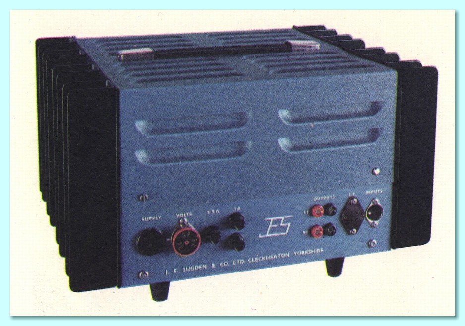
Power (obtained from A51) 35mA at +16V 
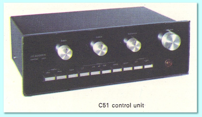
Size 280 x 95 x 170 mm


* Basic sensitivity. But supplied with adaptor to same spec as Magnetic input unless otherwise specified by purchaser.

The tape output specified is for disc input of rated level. The Radio and Aux inputs were connected directly to the tape out when selected.

The A51 was in a larger case than the A21 and employed large external heatsinks. The case was also louvered to allow easier passage of air for cooling purposes. The heatsinks and casework made it possible for the unit to cope with higher power dissipations than the compact A21. The amplifier was a similar design to the A21 series 2. One half of the output pair was driven by inversion of the output from the other. This method works reasonably well with a simple Class A arrangement, but would be unsuitable for Class B! The A51 used different output devices, and a higher rail voltage (55 Volts compared with 35 Volts) than the A21. This rail voltage was also provided by a stabilised power supply which meant the available voltage was better controlled and had less ripple.

A51SmallDiag.gif - 19Kb


The above shows a small version of the circuit diagram for the A51. if you wish to see a larger, more detailed version of the diagram and a list of the components, click here.

The higher rail voltage allowed the A51 to deliver higher Class A powers than the A21 into high impedance loads. The stabilisation also allowed the amplifier to deliver slightly higher sustained output powers when operating beyond its Class A region. However the quiescent current for the A51 was just 0·875 Amps. This was only slightly more than the 0·8 Amps of the A21 Series 2. As a result the A21 actually could provide much the same Class A power into low impedance loads.

When the original A21s and A51s were designed loudspeakers generally had higher impedances than we tend to expect today. Typically in the range between 8 and 16 Ohms. So the main aim for the A51 was to provide higher powers into such loudspeakers. However the A51 design used a single output pair of (2N4914) devices per channel, just like the A12. This meant that the quiescent current which could be used was restricted by the power dissipation these devices could safely handle. With a rail voltage of 55 V and a quiescent current of 0·875 A the power dissipation was just over 45 Watts per channel (i.e. about 23 Watts per output device).

PvsR.gif - 19Kb

The above plot compares the Class A power operating areas of the A51 and A21 Series 2. The maximum (clipping level) power output specified for the A51 was 25 Watts per channel, both channels driven, into either 8 or 15 Ohm loads. However looking at the above plot we can see that the actual area of Class A operation was limited to about 22 Watts into 15 Ohms and just over 12 Watts into 8 Ohms. This is why the distortion specification was for 20 Watts (into 15 Ohms) not the clipping rated level of 25 Watts. It also indicates that the design was able to deliver higher currents and powers than shown in the above plot, but would then be working outside Class A operation.

Today we might expect a high power Class A design to employ paralleled pairs or sets of output devices. This enables higher currents to be used and deliver larger output powers into low impedance loads whilst remaining in Class A. For simple Class A arrangements the result tends to a power amplifier whose standing dissipation may be well above the A51’s 100 Watts. But that wasn’t thought to be necessary at the time the A51 was designed. To some extent this also reflects a difference in the nature of the music which was being reproduced.

In the 1960s and early 1970s the assumption tended to be that high quality music would be either ‘classical’ music, or acoustic recordings of folk, jazz, etc. This was generally recorded without much level compression. The result was recordings with a high peak/average power ratio. Hence the music was mostly replayed with average powers well below the peak the amplifier could produce without clipping. Indeed, one of the main arguments Jim Sugden put forwards for Class A at the time was that it was the “First Watt” that made the difference. The idea being that most of the time you heard signals with the amp producing up to 1 Watt, and that this was the area where Class A scored over the early Class B and AB designs.

Nowdays much of the popular/rock music which is recorded and broadcast is heavily level-compressed and processed, sometimes also heavily clipped. The result is a much smaller peak/average ratio, and music which people wish to ‘play loud’. So the conditions of use in many cases today is quite different to those envisaged at the time Jim Sugden’s early designs were created and sold.


back.gif - 332 byteshome.gif - 1276 bytes