How long is a piece of string?
Note: The page is a technical appendix to another webpage which examines the possible use of mains cables in terms of their RF properties. To understand the context of this appendix you should also read the main page on this topic.
The transmission line model
This appendix provides a simplified explanation of the standard transmission line model of the behaviour of a length of cable. In particular it examines the transmission behaviour when we have a length of cable whose characteristic impedance may not match the impedance of the source or load. The model given here is based on the established standard approach as given in engineering texts[1] [2]
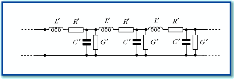
Figure A1
Figure A1 shows the basic model used to represent the behaviour of a single-mode linear transmission line. The values with a prime are assumed to be per unit length. The details of this model are discussed in detail elsewhere. Here we can simply say that the CRLG values are equivalent to two complex values for the characteristic impedance,  , and propagation constant,
  . The relationship is given by the expressions
Note that in general we can expect these values to be frequency dependent and complex.
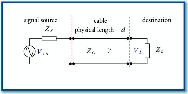
Figure A2
In terms of conventional electronics circuit diagrams can represent a system where a source and load are linked by such a transmission line by the arrangement shown in Figure A2. However an alternative approach is useful if we wish to determine the effect of the transmission line on the (voltage) signal level which appears at the load. This is based on noting the similarity to various other physical systems like stacked optical media or loaded Fabry-Perot Resonators using reflectors with different reflectivity values.
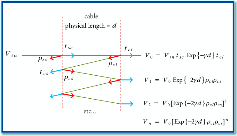
Figure A3
Figure A3 illustrates the physical behaviour of such systems. Here we have two semi-reflecting boundaries spaced apart with a medium whose propagation properties are defined by the propagation constant,  . An input signal (generator voltage from the source),
  , produces a series of signal contributions at the load. Each interface has a (voltage) reflection coefficient. From basic transmission line theory we can say that for the source-cable boundary the reflection and transmission coefficients for a signal incident from the source will be
Similarly, at the cable-load boundary, the equivalent values for a signal incident from the cable onto the source will be
From symmetry, the values for signals propagating in the other direction will experience reflection and transmission constant values of
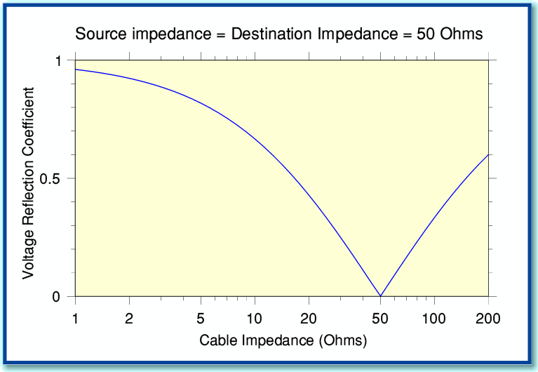
Figure A4
Figure A4 shows how the magnitude of the reflection coefficient varies with cable impedance when the source and/or destination impedance is 50 Ohms. You can see that we get a perfect match (no reflection) when the impedances all share the same value.
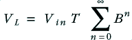
Using these values, we can define the signal contributions reaching the load as shown in Figure A3. The total load voltage experienced will be
where
The above is a standard infinite series which is equivalent to
We can therefore define a voltage gain (actually a loss) ratio when the cable is used
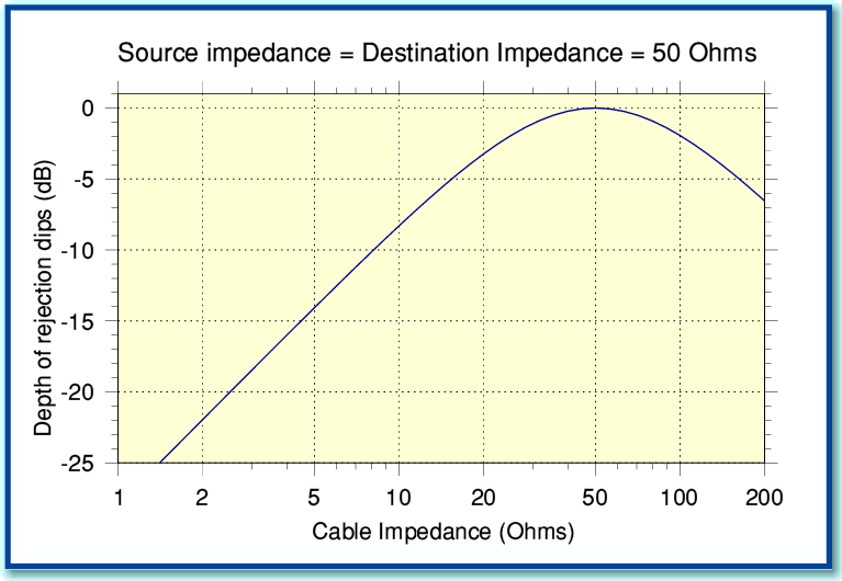
Figure A5
Figure A5 shows how the magnitude of the dips in the reflective behaviour vary with cable impedance when the source and destination are both 50 Ohms. These results assume the inherent losses of the cables are small enough to be ignored.
This value tells us how large the output voltage will be for a given input voltage. When the source and destination (load) impedances have the same value the power transfer efficiency will be given by  . However in cases where the source and destination have different impedances the power transfer efficiency will be
  since the power is determined by the product of voltage and current.
Jim Lesurf
9th Jul 2009
[1] Electromagnetics J. D. Kraus McGraw Hill. 3rd edition ISBN 0-07-Y66380-7
[2] Fields and Waves in Communciation Electronics Ramo, Whinnery, and Van Duzer. Wiley 3rd edition ISBN 0-471-58551-3