Mains Filters for Domestic Audio
Introduction
Ideally, the mains voltage provide by your wall sockets would (in the UK) be a clean 50Hz sinusoid with an rms size of around 240 Volts. Alas, in practice the voltage will vary, and can be accompanied by interference. This may produce unwanted effects like audible bangs or rasping noises from sources like fridges or central heating thermostats. Some audio enthusiasts may not hear any obvious clicks or buzzes, but worry that the sound quality they hear is being ‘degraded’ in subtle ways by the presence of unwanted RFI (Radio Frequency Interference). Hence a significant commercial market has developed, offering various types of mains filter. conditioners, etc, to cater to the wishes of audio fans.
In a perfect world all the makers of equipment that is a source of interference would clean up their acts and there would be no RFI problems. Failing that, my own view is that dealing with the problem is primarily the responsibility of the designers and makers of the audio audio equipment. Quite simply, unless the RFI or spikes are exceptionally severe, audio equipment should be able to reject it. However, the circumstances and levels of interference do vary a great deal in practice. So it is inevitable that in some cases mains filtering may be needed to help block the entry of RFI, spikes, etc, into a HiFi or AV system.
Unfortunately there are a confusing array of ‘solutions’ on offer, from fancy mains cables, though filters of various types, up to units that regenerate a clean mains power supply. The methods used, and the costs, span a wide range. Some methods may be highly effective whilst others may be worthless. This can make it hard for the audio enthusiast to decide which of the possible ‘solutions’ on offer are worth considering.
The main (pun!) aim of this investigation is therefore to look at some of the basics of mains filtering and help audio enthusiasts to make sense of the claims made by manufacturers and sellers. Thus to clear the way to making sensible decisions and appropriate choices. Since I live in the United Kingdom (OK, in Scotland!) I’ll consider the situation there. Some details will be different in other countries, but much of what follows would still apply – allowing for different mains voltages, grounding arrangements, etc.
Basic Passive RFI filtering
In the UK the situation is complicated by various factors. One being that mains power is generally supplied via a three-wire arrangement of Live+Neutral+Earth. But for the sake of clarity I will initially ignore that complication and assume we have a simple two wire mains power connection. I’ll also start by looking at basic filters that use the common types of passive components like inductors, capacitors, and resistors. Many designs of mains filters employ special materials or devices – e.g. ferrite devices – but I have examined their use on another webpage.
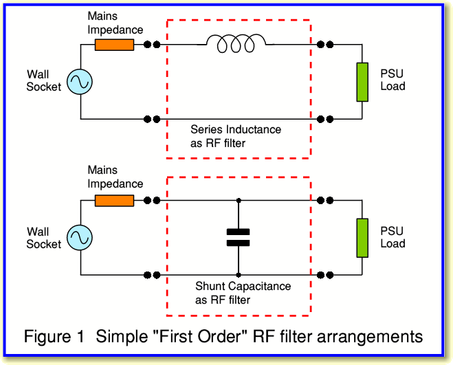
Figure 1 shows two very simple arrangements we could use to help reduce the level of RFI reaching the PSU (Power Supply Unit) of an item like an audio amplifier. One has an inductor in series with the Live wire. The other has a capacitor between Live and Neutral as a ‘shunt’ for RF fluctuations. For simplicity we can initially regard the PSU as being like a resistive load drawing some current, and the mains as an ac source with its own output resistance at the wall socket. Having examined the behaviour in these simple situations we can go on to consider the effects of other complications which arise in practical cases.
Each of the arrangements shown in Figure 1 acts as what engineers would call a ‘First order’ low-pass filter. This ‘order’ can be regarded as indicating the number of frequency-dependent items involved – i.e. one inductor in one case, and one capacitor in the other.
For the sake of example I have chosen to use a 10 microhenry inductor for a series inductance in one filter and a 100 nanofarad capacitor in the other. These values were chosen just to illustrate some aspects of the behaviour of the systems. In practice we might well chose quite different values for reasons that should become clearer later on!
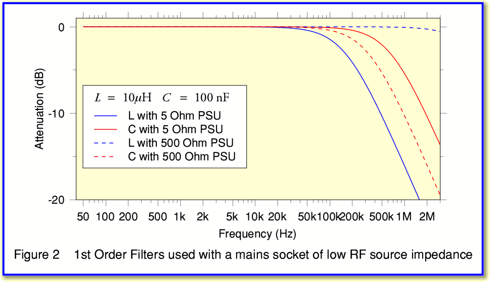
Figure 2 shows the frequency responses the two filters would produce if we had a wall socket whose output (source) impedance at RF was 5 Ohms. The results are shown for a choice of two possible values of the RF impedance of the PSU – 5 Ohms and 500 Ohms. As above, these values were chosen purely for the sake of example.
Looking at the frequency responses in Figure 2 we can see that if the PSU has a low RF impedance then the series inductor gives the most RFI rejection (solid blue lines). However if the PSU has a high RF impedance then the shunt capacitor (broken red line) would give the best rejection. From this example we can see that the choice of which filter might be judged ‘best’ can depend on what value of impedance the PSU presents at RF.
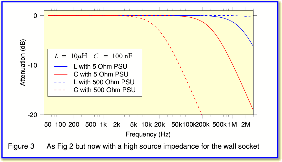
We can now look at Figure 3. This is similar to Figure 2, but in this case a much higher RF source impedance for the wall socket was assumed (100 Ohms). Comparing Figures 2 and 3 you can see that the curves have been re-arranged. Now the shunt capacitor filter gives the most RF rejection for both a 5 Ohm and a 500 Ohm PSU RF input impedance. Of course in practice we can expect the wall socket to have an output impedance that is much smaller than 100 Ohms at 50Hz. But at higher frequencies the socket’s impedance may well be higher. Hence we do need to consider the effects of high wall socket impedance at higher frequencies.
Alas, we usually have no idea what RF impedance value a mains socket will have. It will probably vary with frequency, and from one socket to the next. It may also change as items in another room (or next door) are plugged in or switched on. Secondly, we also have no idea what RF impedance the PSUs of our audio equipment may present. Indeed, to make things worse many PSUs may present an RF impedance that varies during each mains cycle. And in cases like audio power amplifiers, might also vary with the loudness of the music being played. What this all means is that if we use filters as simple as the arrangements shown in Figure 1 we can’t have much idea in advance how well they will work, or what filter component values might be optimum! And this is ignoring the added complications of having three-wire mains, etc... To make things worse, there are also some other factors to take into account...
The inductive filter means we have an inductor in series with the mains supply. This means that the 50Hz mains current also has to pass though the inductor. Now a 50 microhenry inductance only presents a series impedance of a few milliohms at 50 Hz, so isn’t likely to be a problem. But the above filter example is only aimed at reducing RFI at frequencies above the audio range. If we wanted the filter to block clicks and crackles at audible frequencies we’d have to choose a much larger inductor. That would increase the series impedance at 50 Hz, and hence might affect the delivery of the mains power to the PSU.
The shunt capacitance filter will tend to draw 50Hz current from the wall socket even when the PSU of the audio equipment is switched off. Again, with a capacitance of 100 nanofarads the current drawn will small. But as above we might want to use a larger capacitance – and hence draw more 50Hz current – if we wanted the filter to help reject audio frequency clicks and bangs, not just RFI. Hence although simple filters like the above examples can help reject RFI, they are far from ideal. Fortunately we can improve filter performance by using more complicated arrangements.
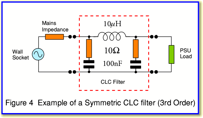
Figure 4 shows an example of a more involved filter that uses three frequency dependent components (two capacitors and one inductor). In this case the filter also includes some resistors in series with the capacitors. The combination of a capacitor and resistor in series like this tends to be called a ‘snubber’. The added resistor helps define the behaviour at RF more clearly. It also allows the filter to absorb some of the unwanted RF energy.
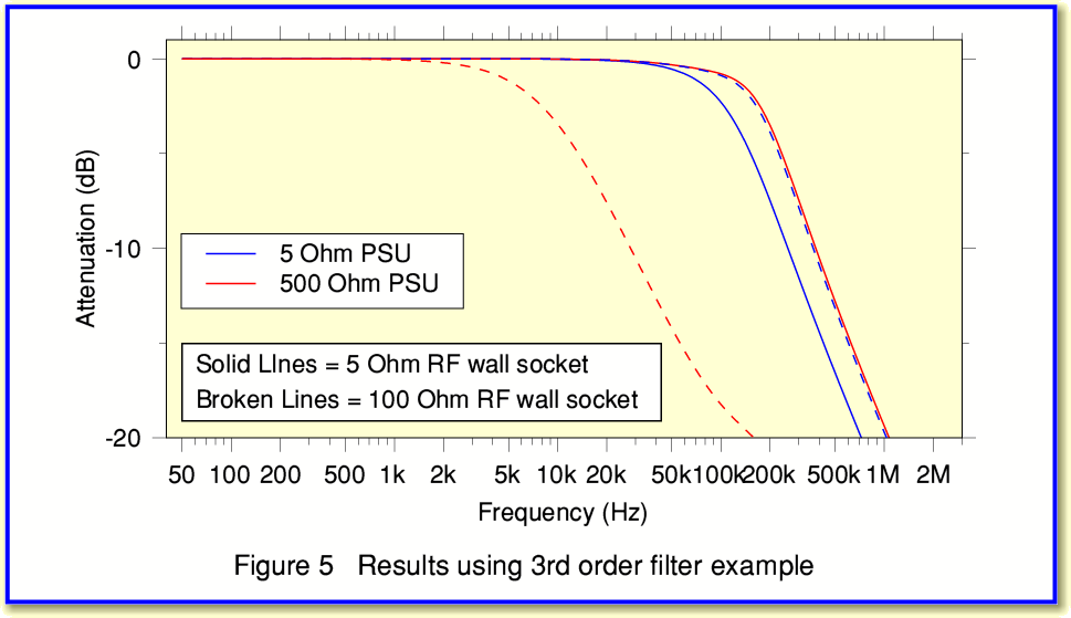
The RFI rejection behaviour of this new filter is shown in Figure 5 using the same values for the assumed wall socket and PSU RF impedances as Figures 2 and 3. If you compare Figure 5 with Figures 2 and 3 you can see that the filter’s effect is now less sensitive to the values of the wall socket and PSU impedances. Hence one advantage of the more complex filter is that it is more likely to work in practice as had been intended! The slope of the increase in rejection with frequency also tends to be steeper than for the 1st order designs. So we can expect it to reject high frequency RFI more effectively.
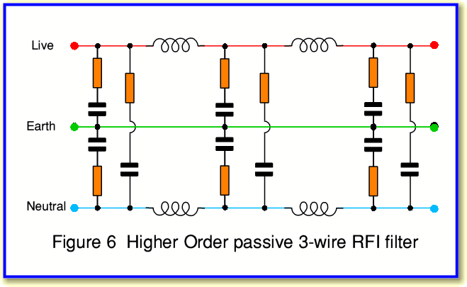
Expensive commercial filters can include a larger number of capacitors and inductors to obtain higher rejection and reduce the sensitivity to mains and PSU RF impedances. Figure 6 shows a possible example of the kind of circuits that could be employed. Note that in this case there are RC snubbers between the Live and Neutral as well as between Live and Earth and between Neutral and Earth.
In practice, well designed filters of this general type can provide high amounts of RFI rejection. But they will still tend to produce the two side effects mentioned above – i.e. putting some series impedance in the 50 Hz path, and causing some ‘leakage’ current to flow even when the PSU of the audio system is switched off. And choosing component values large enough to reject audio frequency interference as well as RFI might mean these side effects become unacceptably high.
In terms of filtering, the advantage of arrangements of the kind shown in Figure 6 is that they tend to ‘tie’ the Live, Neutral, and Earth together at RF. This will tend to block any differences in potential between any of the three wires at RF. The drawback is that the shunt capacitors tend to produce a 50Hz leakage to the Earth. Whereas with the simple two-wire (Live-Neutral) arrangements as illustrated in Figure 1 and 4 any 50 Hz current though the capacitors only affects the Live and Neutral.
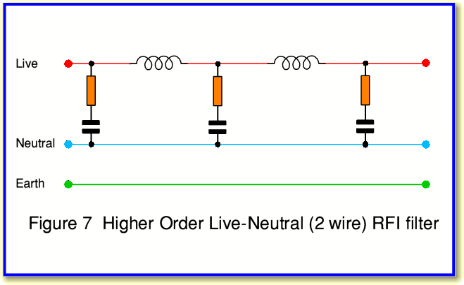
Unfortunately, leakage current to the Earth wire can become a safety issue with UK three-wire mains. This is because if the Earth wire is not correctly grounded it may cause 50Hz voltages to appear on any ‘Earthed’ metalwork. It could also trip a sensor that disconnects mains power when ground current is detected. Hence the amount of capacitance we can employ between the Live or Neutral and the Earth is limited. For this reason it tends to be easier and safer to just filter the Live-Neutral pair so far as employing shunt components are concerned. Hence a more practical arrangement might look in the UK more like the circuit shown in Figure 7. This (minus the Earth wire) is also more suitable for mains filtering in places where no Earth wire is provided. The drawback is that it provides no filtering for any interference which causes the Live and Neutral potentials to vary together (i.e. ‘common mode’) relative to Ground potential.
In practice a real design may be similar the arrangement in Figure 6, but use much smaller capacitors for the shunts to the Earth so as to minimise the 50 Hz ground leakage. This may not work as well as using larger capacitances, but gives some filtering while avoiding the safety problems. Also in practice the components used in mains filters need to be chosen with care to ensure they meet the safety standards which are legal requirements for mains applications.
As I explained at the start of the investigation on this webpage, here I’ve only examined the use of standard passive RCL components. The aim being to give a general understanding of how the filters work and the various requirements involved. The use of special materials and devices is examined on another webpage which you can reach by clicking on the ‘next’ icon below.
Jim Lesurf
24th Mar 2010