500 Series - FAQ Page
This page is to provide some information which may be useful for using a 500 range unit, or to diagnose and fix simple problems that may arise due to aging of the components. Here I will mostly refer to the ‘amplifier’ or ‘tuner’. However bear in mind that the units were modular. Hence the receivers (525 and 526) have the same circuits as the 521 amplifier and 523/524 tuners, so the same comments will generally apply to the relevant sections of the receivers. Please note that the following information is given on the basis that it is your responsibility if you decide to open up your set and do anything to it. Unless you are certain you know what to do, and accept responsibility for what happens, then send a faulty unit to a professional for repair. I do not accept responsibility for any loss or damage that may occur if you open up a set and work on it after reading this page. Also, do not work on a set that is plugged into the mains as this is dangerous.
My amplifier sometimes makes odd noises, or occasionally goes silent. What is causing this, and can I fix the problem? Sometimes faults like this are intermittent, and will appear and vanish if you operate the controls. The ‘odd noises’ may be roaring noises, buzzes, squeaks, etc. The most common causes of these problems are:
- Poor edge-contacts for the circuit boards.
- Poor switch contacts for the front buttons.
- Degraded electrolytic capacitors.
The 500 range units are all of modular construction. They consist of a series of circuit boards which are plugged into edge-connectors. These edge contacts then provide all the electrical connections required. For manufacturing and service purposes this method of construction was quite convenient. For example, if a set had to be sent for repair it could be fixed simply by replacing a faulty board, and then returned promptly to the owner. This meant they got back a working set without waiting for the time required to actually fix the faulty board. The disadvantage is that all ‘mechanical’ contacts tend to degrade with time. As a result, the electrical contacts may become imperfect.
A similar problem afflicts all types of mechanical signal switches. Their contacts wear and corrode, and the springs that push the contacts together tend to soften.
As these contacts degrade, the performance may be affected. In particular, the 500 range pre-amplifier has its feedback altered by some of the switches on the front panel. If these switches - or the edge contacts they are wired to - degrade, then the amplifier may act as an oscillator. You can tell if it is the pre-amplifier section that is causing this problem if the loudness of the strange noises can be reduced by turning down the volume control. If it occurs on one channel, then it will be the pre-amp for that channel which is experiencing the problem.
It is sometimes possible to fix this problem by cleaning the relevant contacts. This does not require much technical knowledge, but must be done with care as otherwise you may cause some damage. If you wish to try this, then the following information may be of use as a guide:
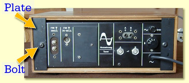
First you have to remove the unit's wooden case. Make sure you have disconnected the unit from the mains power before proceeding. The wooden case is held in place by a pair of large bolts which hold a pair of vertical metal plates at the left and right ends of the back of the set. Undo the bolts and remove the bolts and bars.
The above photo shows the back of a 524 tuner. There is bolt and plate on each side at the back. The other units in the 500 range all use the same arrangement.
It should now be possible to pull the chassis out of the front of the case. Please note when doing this to take care that any sharp objects inside the set do not catch or scratch the inside of the wooden case. In particular, take care with the underside as there may be protruding soldered wires here that will scrape inside the case. I tend to place the case on its side before removing the chassis as this reduces the chances of doing damage.
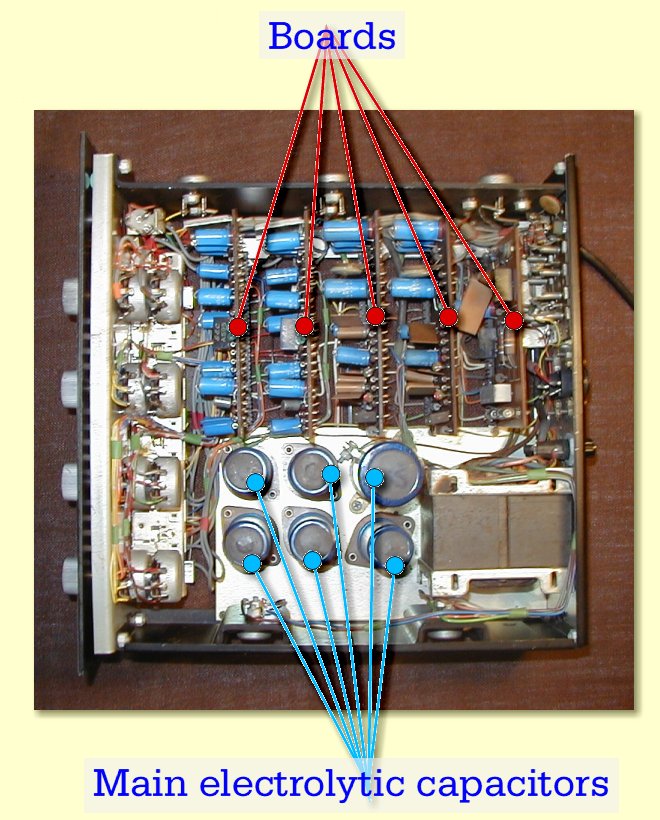
Having removed the chassis from the case you may find it is covered with dust and dirt. if so, give the unit a good vacuum clean and/or brush. Now examine the electrolytic capacitors. In particular, the large vertical ones that are usually coloured blue. These may show signs of having ‘leaked’. If so, the deterioration may be due to this, and they might need replacing. One end of the capacitor will have a rubbery covering with a small area which may have bulged or burst. Electrolytic capacitors tend to deteriorate with age. Despite visible signs of distress they may still be working fine, but of course they may not. If you see that ‘goo’ has been leaking out from a capacitor then it may be advisable to replace it. However this may not be necessary, so you only need to consider this if cleaning the set does not solve problems. Note, though, that the goo is corrosive, so should be cleaned off metal parts, and you should avoid getting it on your fingers, etc.
Carefully remove each circuit board for cleaning. Note that you may have a top-bar running the length of the boards, holding them in place. These were fitted originally to help keep the boards firmly in place. However experience shows that many of these seem to have vanished by now! Before removing each board make a note of which way around they are, and which board in is which holder. Each board should have a ‘slot and key’ which is designed to ensure that you can only fit the correct board in each connector, the right way around. However, noting the above means re-assembly is quicker and easier. There is also a possibility that some units may have lost a key! It is sometimes best remove the board by carefully pulling and lifting each end in turn so as to ease it gently from the socket. You need to take care as sometimes the contact becomes very tight and there is a risk of breaking the actual connector loose from the chassis.
You may now see signs of corrosion or wear on the edge-contacts. This may take the form of a black stripe along each contact.To clean the contacts you would ideally use solvent sold for this purpose. However alcohol, vodka, or even a good malt whisky will do! Clean with a cotton bud (Q tip) or similar, dipped in the solvent. This should remove muck that is then visible as a discolouration of the cotton bud.
If you can obtain an aerosol can of 'contact/switch cleaner' you can spray this into the switches and the volume pot, etc whilst operating them a few times. This will clean them. With old units is usually a good idea to do this, but you should generally avoid using any sprays that leave a coating. You can now fit the boards back into the set, fit the case, and see if the problem has been solved.
The amplifier makes a scraping or roaring noise when I adjust the volume control. Or: The signal seems to jump to a louder or quieter level in an odd way. What causes this? This usually is due to a problem with the volume control, but sometimes affects other controls. It us due to corrosion or wear of the potentiometer. As the control is rotates it scrapes a metal wiper along a resistive track inside the control. With use, this can wear down, become corroded, etc. The early pots sometimes wore through the thin layer of resistive material which came loose.
It is often possible to cure this by spraying a suitable contact cleaner solution into the potentiometer whilst operating the control a few times. To do this you need to disconnect the set from the mains and remove the case as described above. I would usually recommend an aerosol cleaning spray that does not leave any residue. However in cases where this does not work you might consider trying (at your own risk!) a procedure that Armstrong used to employ back in the 1960's. This was to spray a tiny amount of light oil into the potentiometer. This lubricated and softened the surface and reformed a smooth track. However this method is “kill or cure” and may ruin the potentiometer, so only try it as a last resort before deciding the control has to be be replaced! Also, take great care not to drop oil elsewhere in the set!
I have obtained an amplifier and it uses a strange type of loudspeaker plug that I have not seen before. Where can I get one of these?
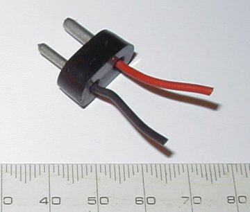 The 500 used a type of round-pin asymmetric plug/socket that was quite common in the 1960's. A photo of one of the required plugs is show on the left. Alas, this design of plug and socket became obsolete during the 1970's and they are now quite rare. You may be able to find some by asking dealers who specialise in old radios and second-hand valve equipment. Alternatively, you may be able to use a pair of small plugs or split pins. In some cases, owners have removed the old sockets and replaced them with something more useful due to not being able to find satisfactory plugs.
My amplifier seems to have died altogether. I think the output transistors have failed. Can I replace them? The output transistors used in the 500 range were AL102's. These are germanium transistors and are now obsolete. Many of the other transistors used are also germanium. Most modern transistors are made from silicon, and have detailed behaviour that is different to the old germanium types. If you are lucky you may be able to find replacement AL102's, however this is doubtful, and they would probably now be expensive. Hence if one or more AL102 has failed and you wish to repair the set you would need to replace the transistor with a modern silicon power transistor. This requires the circuits to be modified, so requires skilled modifications.
Alas, early germanium transistors tended to be unreliable, and their performance and durability varied unpredictably from one individual transistor to the next. This was due to the poorer transistor manufacturing standards which were available at the time. Hence the failure rate for AL102's was higher than we would now find acceptable. They were/are also very sensitive and prone to fail if the current or power levels rose too high, even briefly. The good news is that if your amplifier does still work then its transistors were probably examples of the more reliable ones made, so used with care, they should go on working.
My tuner seems not to work correctly. The sound never seems to be in stereo. Is something wrong? The 500 tuners are capable of receiving FM stereo. There is an indicator light on the front panel that should light up when stereo is being received. If the light comes on, but the sound does not seem to be in stereo, then check that the ‘mono’ button is not pressed in. This bypasses the stereo decoder and is designed for use when the signal is weak and mono gives a better signal-to-noise level.
If the indicator does not light up it may be that no stereo decoder is fitted to the unit. Remove the case (see the instructions for this given near the top of the page.) Look to see if a decoder board is present. If it is not, then a decoder is required. When the 500 range was produced stereo transmission were rare in the UK, and were only broadcast in a few areas of the country. Hence the decoder was an optional extra.
If a decoder is present, but no stereo is heard, then the unit may be faulty. Checking this will probably require professional attention from someone who has the required equipment. However, it may be worth trying removing the decoder board (as described near the top of this page) and cleaning it.
 Content and pages maintained by: Jim Lesurf
using HTMLEdit and TechWriter on a StrongARM powered RISCOS machine.