The Armstrong 524 FM Tuner
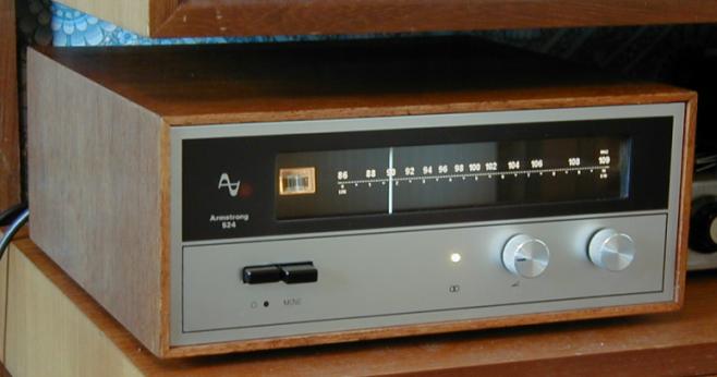
The photograph above shows a 524 FM tuner in use. The tuner shown is a late model with the rounded buttons. Since the 500 range is modular, the slot-in cards used in this tuner were the same as in other units in the range. The tuner has both 75 Ohm (co-axial) and 300 Ohm inputs for FM. The output is via a pair of RCA/phono sockets and the output level is adjustable using a pair of 1 kOhm pots on the back of the set. The wooden case for the tuner is essentially the same as that for the amplifier.
To the left of the tuning scale a center-zero tuning meter is provided. The tuner does not include a signal strength meter. The knob furthest to the right is for tuning. The knob to its left (which has an indicator line on its front) sets the level of a ‘mute’ circuit which is provided to allow the user to stop hiss being audible in between stations. Depending upon the level at which this is set, the control can also be used to reject weaker station that do not provide an acceptable signal-to-noise performance.
The button on the left is the on/off switch. Immediately to its right is a stereo defeat (mono) selector. Due to way FM stereo works, good quality stereo reception requires a much higher input signal level than is needed for mono. The defeat button allows the user to choose to listen in mono when this this is judged to provide improved reception. When stereo signals are being received an indicator light comes on. This light is on in the photograph and can be seen to be located midway between the buttons and the control knobs, below the tuning scale.
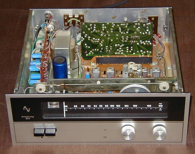
The above photograph shows a view looking into the 524 chassis with its wooden case removed. The RF and IF stages are on the main board which covers the bottom of the set. The power supply is to the left when looking (as here) from the front. At the far left of the box (i.e. to the left of the mains transformer) is the C22 control board. This carries the output audio amplifiers and the regulated power supply components. The stereo decoder is the board that is standing vertically towards the back of the chassis with its green coloured track side towards the camera. The decoder was an optional extra as when the 500 range went on sale stereo broadcasts were rare in the UK, and did not cover the entire country.
So far as the user was concerned the 523 AM/FM tuner looked very similar to the 524. The only visible changes were an extra trio of buttons to select VHF/MW/LW and two extra tuning scales for MW and LW. The chassis and wooden case where the same overall size and appearance as for the 524. Inside the box the chassis arrangement was slightly different as can be seen by looking at the diagram shown above. The AM sections were place on the main board behind the FM sections. To make room for these the location of the stereo decoder board was moved from the back of the set to the right of the power supply. The layout of the tuner sections in the 525 and 526 receivers also followed the same layouts as shown here.
 Content and pages maintained by: Jim Lesurf
using HTMLEdit and TechWriter on a StrongARM powered RISCOS machine.