The Armstrong 500 Series
The 500 was perhaps the Armstrong series that sold best. At one time over 50 percent of 521 amplifiers were being sold via the ‘Comet’ chain of discount warehouses. They were used by Comet almost as a loss-leader since people would come in to buy a 521, then purchase suitable loudspeakers, etc.
The units were:
- 521 Amplifier
- 523 AM/FM Tuner
- 524 FM Tuner
- 525 FM Receiver
- 526 AM/FM Receiver
The units were modular so the same amplifier and tuner circuits were used throughout the range.
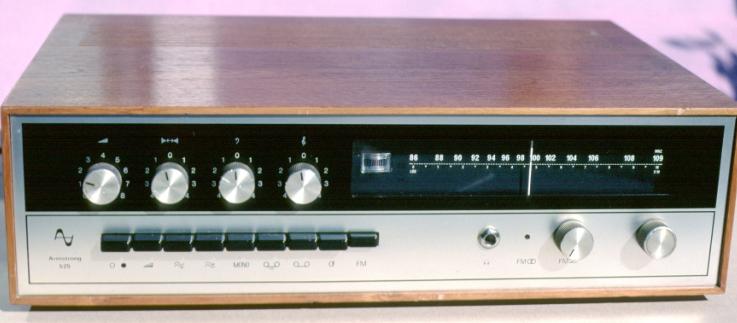
The above picture shows a front view of the 525 FM Receiver. The styling can be seen to be more conventional than the earlier 400 range. A brushed aluminium front with transfer details printed in black. The wooden box was teak finished. It is possible to identify this example as being a late model as the front buttons have rounded edges. Earlier models had square-edged buttons. The 526 AM/FM Receiver has a very similar appearance and the same performance, but adds MW and LW reception.
500 Range FM Tuner Specifications
| Coverage
| 89 - 109 MHz
| Frequency Response
| 30Hz - 15kHz ±1dB
|
| Sensitivity (30dB SNR)
| 1·5 microV (mono)
| 5 microV (stereo)
| (for 75kHz dev.)
|
| IF
| 10·5MHz center
| 220kHz bw (-6dB points)
|
|
| Channel separation
| >30dB at 1 kHz
| SNR (>1mV in)
| >60dB
|
The AM section of the tuner provided both MW and LW bands. Stereo VHF was catered for by the 'M8' decoder. This could be included when the tuner or receiver was first purchased. Alternatively, it could be bought and fitted at later date by the user. The design of all the units was based on a set of PCB cards that could be slotted in and removed. This made the system quite flexible to manufacture and meant that any units sent for repair could often be ‘fixed’ quickly. As a result if an owner whose set had developed a fault brought it to the factory it could often be give back to them in working condition in the time taken for them to have a cup of tea! The company advertised that it had a '48 hour' maximum time for repair work. Most of the time this was easily exceeded and any delays tended to be due to delivery.
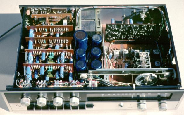
The above picture shows the internal layout of the circuit boards in a 500 range receiver. The power supply is in the middle. The amplifier boards are to the left, and the tuner to the right. In the 525 (and 524 tuner) the M8 decoder board is located just to the right of the power supply and runs back-front of the box, not right-left as do the amplifier boards.
The 500 range amplifier was rated at 25 Watts per channel continuous into 8 Ohms. As with the 400 range the output devices were AL102's (germanium transistors)
500 Range Amplifier Specifications
| Rated Power
| 25W per channel into 8 Ohms
| Crosstalk
| <-40dB
|
| Frequency Response
| 20Hz - 20kHz ±1dB
|
|
|
| Total Harmonic Distortion
| <0·5% at 25W
| <0·1% at 1W
|
|
| SNR
| -70dB (tape i/p)
| -60dB (radio i/p)
| -55dB (RIAA i/p)
|
Most amplifiers and tuners gave good service. The sound quality and technical performance were competitive for the time. The main problems with units were due to occasional poor contacts with the edge connectors of the removable circuit boards and the AL102's. The power transistors available in those far-off days were very inconsistent. The gains, etc, could vary by a factor of two or more from one transistor to the next. They also were prone to thermal runaway and secondary breakdown if used at high powers for long periods into difficult loudspeaker loads. Most devices and amplifiers were fine, but some of the weaker AL102's failed in use and had to be replaced.
Photographs on this page © Alan Ralph.
Used by kind permission.
 Content and pages maintained by: Jim Lesurf
using HTMLEdit and TechWriter on a StrongARM powered RISCOS machine.