The Armstrong 521 Amplifier
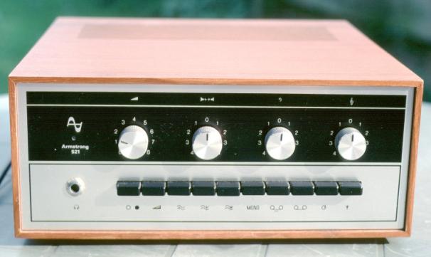
The 521 received enthusiastic reviews in Hi-Fi magazines, both in the UK and elsewhere. As well as offering good performance it was seen as providing value for money and excellent styling. The 500 units also were given a UK Design Council award for their appearance and ergonomics.
As was common in those days, the amplifier provided (Baxandall type) tone controls plus a pair of low-pass filters and a ‘rumble’ high-pass filter. There was also a ‘loudness’ button. This was an attenuator that contoured the frequency response. It lowered the mid-range frequencies by around 20dB, but high and low frequencies by a lesser amount. This was because the commonly accepted theory at the time was that for low-level listening this gave a better sound.
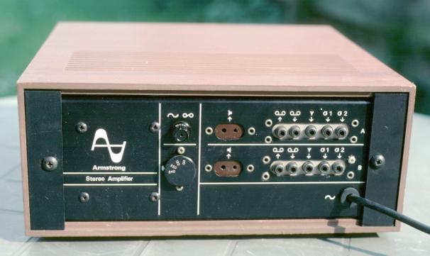
There were RCA Phono inputs for LP/Disc, radio tuner, and tape. There was also a tape monitor output. The loudspeaker outputs were via a pair of assymetric sockets similar to those used on other amplifiers of the period such as those from Leak. These days, plugs for these sockets are rare, so if you ever buy or are given a 500 series amplifier try and make sure you also get a pair of the loudspeaker plugs that fit these sockets!
Electronically, the 500 range was very similar to the 400 range. The amplifier and tuner circuits were almost the same. The improvements were due in part to minor changes and some better components. The higher power rating was partly due to the stabilised power supply unit the 500 range used for the power amplifier stages.
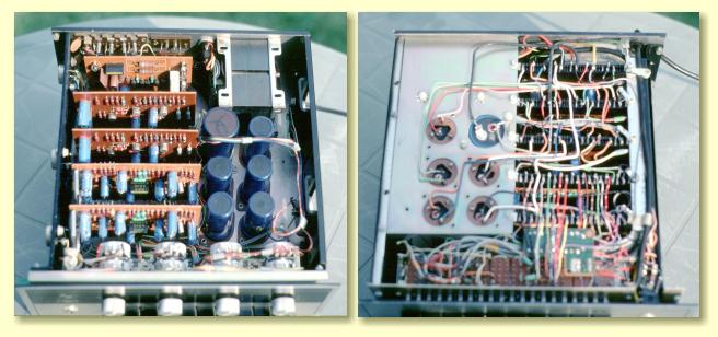
The above photos show a top and bottom view of a 521. You can see the output devices mounted on the metal sides of the chassis. Note that there are five devices — two output devices per channel, and one extra device that is the series regulator transistor of the stabilised power supply. The left-hand photo shows the series of removable circuit boards. These were secured with a top rail stretching from from to back across the tops of the boards, near the left-hand end of the box. This held the cards firmly in place. The right-hand photo shows the wiring that linked the edge-connector sockets into the rest of the circuitry. Again, as was common in those days, you could purchase the units with or without a wooden case.
In design terms the 521 has become a classic that represents the look and sound of late 1960's amplifiers. The circuit had evolved beyond early transistor designs and had left behind their crossover distortion problems. The appearance was tidy and elegant, but unpretentious.
Photographs on this page © Alan Ralph.
Used by kind permission.
 Content and pages maintained by: Jim Lesurf
using HTMLEdit and TechWriter on a StrongARM powered RISCOS machine.