Keep in Contact
In recent issues I’ve looked at the effects that tend to limit the level of the loudest sounds which can be conveyed by FM radio and CD. But what about the vinyl LP?
As you might expect, many people have studied the performance of LP. Older readers may recall work by Stanley Kelly and others[1][2][3][4][5]. Indeed, so many articles have appeared in Hi Fi News over the years that I decided it would be impractical to start listing them here! For that reason the references I’ve given are just a few selected items. However, things move on. Technological developments mean that modern cartridges using styli with ingenious shapes and advanced materials have advantages over the old spherical-tip beasts of the mono era. Also, I suspect that most current readers of Hi Fi News won’t have access to journals from decades ago, and may be unaware of the details. With this, and the continued enthusiasm for LP in mind, it seems worthwhile to revisit the topic and examine it in the light of current technology.
Let’s start from the basics. Figure 1 shows the standard RIAA (Recording Industry Association of America) replay curve which is used for all modern LPs. This shows how the gain of the LP replay system is expected to vary with audio frequency.
 Figure 1
For LP, the convention is that signal levels are defined in terms of the sideways (modulation) velocity of the stylus. And that the 0dB reference level shall correspond to a peak velocity of 5 cm/sec for a 1 kHz sinewave. If we combine these defined standards with the RIAA curve we can work out what velocity is required for a 0dB level as a function of audio frequency. The results are illustrated in Figure 2.
At high frequencies the replay gain is much lower than at 1 kHz. This means higher velocities will be required in order to get the same output level. So although only 5 cm/sec is needed for 0dB at 1 kHz, we require around 45 cm/sec to provide 0dB at 20kHz.
 Figure 2
In practice, there is a limit to the maximum velocity which can be cut onto an LP. The basic reason for this can be understood by looking at Figure 3.
 Figure 3
This shows the cutter being used to cut the groove onto the disc. The cutter is essentially a type of chisel with a flat front-face and back faces which are angled so as to avoid them touching the groove walls which have just been cut. The disc is rotated to draw the cutter though the material with a chosen forward cutting velocity. The sounds to be recorded then generate a pattern of sideways modulation velocity variations that determine the groove shape on the LP. The modulation means that the cutter tends to move at a varying angle to the direction of disc rotation. The larger the modulation velocity relative to the cutting velocity, the steeper this modulation angle at a given location along the groove. However we have to be careful. If the modulation velocity becomes too large. We then find that the back face of the cutter would dig into the groove walls immediately after the front face has cut them. This would damage the groove shape and distort the recorded sounds.
The maximum modulation velocity we can safely use is set by the cutting velocity – determined by the disc rotation past the cutter – and the angle between the front and rear facets of the cutter. The cutter shape may differ from one LP lathe system to another, but for the sake of example we can assume that the angle is around 40 degrees.
The cutting velocity depends on the rotation rate and how far the cutter is from the center of rotation. This is illustrated in Figure 4 which shows the standard values for a vinyl LP[6]. At the start of the recording the distance from the center will be apprximately 146 mm, and the cutting/replay velocity will be 51 cm/sec. By the time we reach the end of the recording the distance from the center may be approaching 56 mm and the cutting velocity will be down to less than 20 cm/sec.
 Figure 4
Assuming the cutter has a back angle of around 40 degrees, this means we can’t cut modulations above approximately 60 cm/sec at the start of the LP side, falling to around 24 cm/sec at the end of a side. Note that these limits have nothing to do with the replay system. They are a function of the geometry of the cutting arrangements and the standards for vinyl LP. The result is that there will be a limit to the peak velocities it is possible to record onto the LP.
 Figure 5
Having considered the situation in terms of modulation velocity, lets now consider the sideways displacements required for modulations at the 0dB level. These are plotted in Figure 5. Here we find the opposite behaviour to when we considered velocity. The displacement required for a given sound output level increases when we reduce the frequency. The reason for this is that each half-cycle of a lower frequency has a longer duration. A given modulation velocity therefore has more time during each half-cycle to build up a large displacement before it is then reversed during the next half cycle. For frequencies around a kHz or higher the displacements tend to be modest. But we need much larger displacements to record 0dB levels at low frequencies. Over +/-40 microns is required to be able to record a 0dB sinewave at 20Hz. Alas, large displacements can lead to problems...
 Figure 6
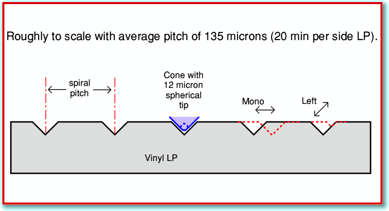
Figure 6 represents a cross-section through a typical LP. If we assume that around 20 minutes of music was recorded onto the LP side, then the disc had to rotate 666 times. This means that – on average – the pitch (distance between adjacent turns of the spiral cut) will be around 135 microns. Fairly clearly, the pitch places an upper limit on the horizontal (mono or central sounds in stereo) displacements we can cut before the groove pattern for one rotation would cut into a neighbour! The physical width of the top of the groove means that we have to keep the peak horizontal displacements to somewhat less than half the pitch. So with a pitch of 135 microns, displacements above around 40 microns might cause problems.
A longer playing time means a smaller spiral pitch, imposing a reduced limit on the peak displacements. (Note that the term ‘pitch’ here is nothing to do with the perceived frequencies of the sounds. It just refers to the average spacing between successive rotations of the spiral groove shape!)
Anyone who is already familiar with LP cutting will know that it has been common practice to dynamically vary the spiral pitch as an LP is made. The spiral pitch is increased just before a loud passage starts, and reduced again when the sound level falls. In effect, the rotations of the spiral are packed close together during quiet passages in order to free more space for larger displacements during loud parts of the music. Such dynamic variations can allow greater peak deviations for a given side duration.
However there are some snags. Firstly, it means the actual signal to be cut onto the disc has to be delayed to give time for the pitch to be changed before a sudden loud sound reaches the cutter. This delay used to be something like an analogue tape loop. which could degrade the sound. Secondly, many pop/rock music recordings tend to be relentlessly loud. And in recent years would also have been heavily level compressed. The result being that there often aren’t any ‘quiet periods’ which could be cut with a small pitch to make more room for occasional louder passages of music. Some jazz or classical music does have long quiet sections, but there the commercial pressure is often on to get longer side durations than 20 mins. The real enemy then becomes background noise during quiet sections – thus prompting the decision to cut at a slightly higher level, leading us back towards level compression or a reduction in playing time.
As a result, although some special LPs can be cut with much larger peak displacements, for normal commercial LPs the maximum deviations can be expected to be limited to well below +/-100 microns, and probably below +/-50 microns. This has little effect for high frequencies. But below a few hundred Hertz it can severely limit the maximum sound level which can be recorded in practice.
The above considers sideways displacements in the plane of the disc surface. These represent any mono or L+R sounds. Stereo also requires the groove depth to be varied. Here the geometric limits are twofold. One limit is as the groove depth increases so its width at the vinyl surface also increases – eating into the space left between adjacent turns of the spiral. The other is that we can’t reduce the depth to less than zero! Indeed, the stylus needs a minimum groove depth to be able to sit with its intended contact areas in the groove. So in practice the peak deviations in the vertical (L-R or difference) direction will also tend to be limited – perhaps more so that the horizontal displacements.
 Figure 7
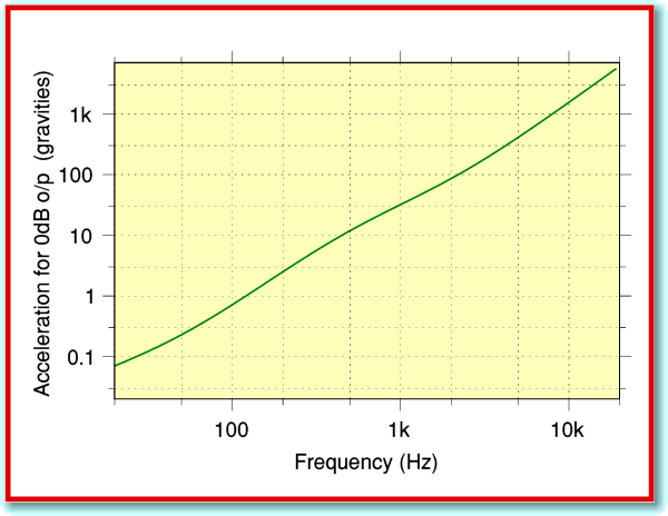
Let’s now consider what levels of acceleration the cutter – and hence stylus – have to endure. The acceleration for our 0dB sound level is shown in figure 7. Note that the required level varies so much across the audio band that I had to plot this with a nonlinear (logarithmic) vertical scale to be able to show what happens! The values here are plotted in terms of ‘gravities’. i.e. compared with the acceleration an object undergoes if you allow it to drop off your desk. At 1 kHz the accelerations required for a 0dB sound are just over 30 gravities. For low frequencies the accelerations are quite small. But up at 20kHz we need to accelerate the cutter (and stylus) at rates equivalents to over 6000 gravities. This is an alarmingly high acceleration, well beyond the wildest dreams of “Top Gear” presenters!
Any stylus will have an effective tip mass. This represents the inertial mass it presents to any acceleration, and determines the force needed to obtain the acceleration. Many years ago it was routine for people to specify or measure the tip mass value of a stylus. Alas, nowdays manufacturers and reviews rarely mention the tip mass value of a stylus.
Consider a stylus with a tip mass of 1 milligram (mg) which is being accelerated at 1000 gravities by the groove modulations . The force required is proportional to the mass times the acceleration. So the force being applied to the stylus by the groove modulations is the same as would be needed to accelerate 1 gram at one gravity. The stylus is pressed down in the groove by the playing ‘weight’ or downforce. If the playing weight is only 1 gram, then the stylus is experiencing forces due to the modulation accelleration that are equal to that which are holding it down in contact with the groove. If the acceleration (or tip mass) is increased, then the groove accelerations will produce forces larger than the playing weight. The stylus can then be flung out of the groove by the recording. For a 0dB 20kHz tone the stylus has to ensure peak accelerations of 6126 gravities. If we assume a playing downforce of 1·5 grams we find that the tip mass has to be less than 0·25 milligrams if we want the stylus to play the tone without engaging in behaviour more appropriate for Olympic ski jumping events.
 Figure 8
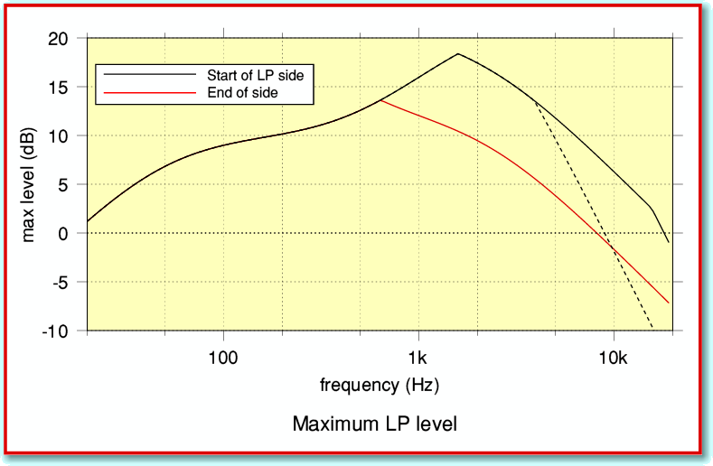
The effects I’ve described here aren’t the only ones that limit what can be recorded and replayed, but they give us a decent basis for an initial estimate of the maximum levels we can expect. The consequences are summarised by the graphs in Figure 8. This shows how the amplitude, velocity, and acceleration effects we have considered limit the maximum signal level at various frequencies. The solid black line shows the limitations at the start of an LP side cut with 50 micron maximum displacement and using a stylus of 0·25 mg tip mass played with a downforce of 1·25 grams. The red line shows the limits at the end of the LP side where the cutting velocity is lower. The broken line shows the consequence if the tip mass were 1 mg instead of 0·25mg. This illusrates why low tip mass is desirable! It can be seen that by the end of the LP side the maximum allowed audio modulation level for high frequencies can be well below 0dB. As before, I assumed a cutter with a backangle of 40 degrees.
I hope to examine some of the other limiting effects in a future article. However next month I’ll look at the levels that actually occur on some typical LPs and compare them with the limits predicted using the arguments in this article.
Jim Lesurf
2250 Words
27th Aug 2007
[1] Record Reproduction. Stanley Kelly. Series in Hi Fi News starting with Oct. 1957 issue
[2] Stereo from Discs. John Goddard HiFi Yearbook 1963 pp 11-16
[3] Pickups Today. Stanley Kelly HiFi Yearbook 1966/7 pp 5 - 11
[4] Measuring Gramophone Pickup Performance. John Walton Wireless World Dec. 1967 pp 581 - 588
[5] Stereo Gramophone Pickups. Stanley Kelly Wireless World Dec. 1969 pp 548 - 555
[6] How to Align a Pickup Cartridge. Keith Howard HFN Jan. 2007 pp 90 - 93


