Many audiophiles will recognise the name Jim Sugden, and the brand he created. They’ll also know their reputations are founded on producing almost legendary designs for amplifiers. But the part Hi Fi News played in the story is less well known...
In the UK ‘Sugden’ has become virtually a synonym for ‘Solid State Class A power amplifiers’. Jim Sugden had been working as an engineer and producer of technical equipment in the early 1960’s. At that time the first solid state amplifiers were starting to appear, but in many cases their audio performance left much to be desired. The phrase “transistor sound” started to appear in audio circles, and mean a harsh sound with poorer fidelity than the valve amps that had dominated the market.
The difficulty was partly due to the relatively poor characteristics of the transistors available and partly due to designers lacking experience with using new-fangled transistors rather than valves. The problem was identified as what came to be called ‘crossover distortion’. The early ‘Class B’ designs minimised the currents and powers the fragile output transistors had to endure, but this meant that each time the signal crossed from a positive to negative sign, one transistor had to be switched off as the other was switched on. This ‘handing over of the baton’ had to be done smoothly, but the devices tended to fumble the pass.
There were also various other lesser-known problems which designers (and customers!) had to discover by frustrating experience. For example, when the temperature of the transistors change it alters the amount of current they conduct when fed with a given signal. This can make it even harder to keep the devices working together as intended. The result could all too easily be a high amounts of distortion – particularly for low level sounds – and performance that wandered around in use. In some extreme cases a vicious circle could occur where as the amplifier warmed up the currents inside it rose, warming the amp still further, thus increasing the current... until the amplifier failed due to overheating or excess current.
 Early transistors were also very unpredictable in quality and behaviour. Picking two out of a bin with the same part number on them was no guarantee that they would behave in the same way in use! Amplifier engineers attacked the problems in assorted ways, with varying amounts of success. Then, in the November 1967[1] and March 1968[2] issues of Hi Fi News, Jim Sugden published two articles which outlined the problems and how they could be overcome using a Class A approach. In these articles he compared various commercial amplifiers with two of his own designs, the Si403 (Class B) and Si402 (Class A).
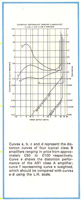
In Class A the output transistors always conduct in normal use, and don’t have to switch on/off. This removed the need for the clumsy early transistors to pass the baton without a fumble, and used the devices on a more linear part of their gain curves. The results published in Hi Fi News clearly showed the Class A design had distortion levels which vanished smoothly at low signal levels, whereas the Class B design did not! A problem at the time was that some of the firms who were developing Class B designs didn’t carefully check the distortion performance at power levels well below 1 Watt. Indeed, some of them didn’t even have instruments that could measure this and give a meaningful result! For those accustomed to valve design this problem wasn’t even ‘on the radar’ as it wouldn’t arise with most widely used valve designs.
Jim ran a company that specialised in laboratory and test equipment, not consumer audio. One of the things he had to do in order to compare Class B and Class A amplifiers at low output levels was to produce improved test and measurement equipment. At the time he sold items as varied as atomic radiation sources and lab kit for use in school/university physics. This was joined by equipment like the Si453 Low Distortion Audio Oscillator and Si 452 Distortion Kit which were advertised in Hi Fi News under the JES Audio Instrumentation name.
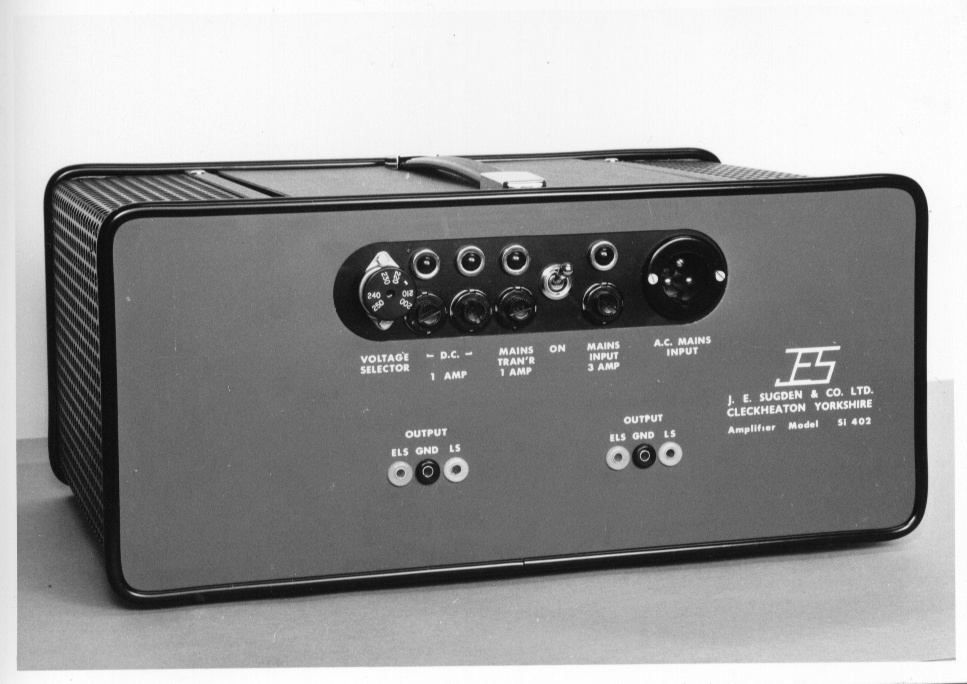
J. E. Sugden Si 402
He also began to make a version of the Si402 Class A power amp, and a matching Si401 pre-amp. But these were designed and priced more as items of professional equipment than as domestic Hi-Fi. At this point Richard Allan, the loudspeaker manufacturers became involved. The results appeared at the April 1968 Audio Fair in the Hotel Russell, London. There Richard Allan proudly displayed the A21 integrated amp, and the C41/A41 pre/power amp, designed by Sugden. As the show marked their 21st birthday as a loudspeaker maker, their new venture made the event something of a celebration all around, and the sounds produced gathered praise in reports on the show.
Around a year later the A21 and the C51/A51 appeared under Jim’s own J. E. Sugden brand name, with the A21 swiftly becoming the A21/Series 2. The initial leaflets for these have the same maker’s address as the Richard Allan leaflets, and the designs look almost identical. There were some changes, though, as witnessed by the fact that the JES Series 2 designs were rated at slightly higher power levels than the Richard Allan version.
The early Sugden design used a pair of diodes with each output device to control the thermal drift in behaviour of early transistors. The output transistors, diodes, and associated bias resistors were all carefully selected to ensure that each amplifier operated exactly as designed. One person was employed full-time, measuring the vital components, and sorting them into boxes ready for use as matched sets! This was the result of the bitter experience of other designers who found that many an amplifier could be made to work OK as a prototype. But when you made them on a production line, every one might perform quite differently to its brothers.
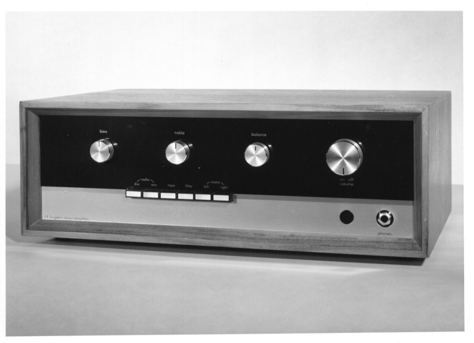
Early version of the J. E. Sugden A21 Amplifier
After the first year or so the ‘series 2’ version of Sugden’s amp went on sale as experience had shown how to get improved, more predictable performance from a simpler circuit.
Alas, as is ever the case with real-world engineering, you can’t get “Owt for Nowt”. Class A has its own limitations. The most obvious of these is that in Class A a lot of power and current is wasted, passing though both output devices even when there is no output signal. Table 1 lists the relevant values for early versions of the A21.
Tables of amplifier details for early ‘A21’ versions
| Model
|
Power
Output (W)
|
Bias
Current(A)
|
Rail
Voltage (V)
|
Total Power
dissipated (W)
|
o/p Devices
|
| RA A21
|
10 into 6 Ohms
|
0.9
|
32
|
60
|
BD121
|
| JES A21
|
10 into 6 Ohms
|
0.9
|
32
|
60
|
BD121
|
| JES A21/II
|
12 into 8 Ohms
|
0.85
|
35
|
70
|
BDY38
|
| HFN Amp
|
12.5 into 8 Ohms
|
0.85
|
36
|
70
|
BDY38 or equiv.
|
The articles sparked a number of letters from readers eagerly requesting information on how to build their own Class A amplifiers. As a result Hi Fi News invited Sugden to publish a design. This duly appeared in the April[3] and May[4] 1970 issues. These articles explained the operation of the chosen circuit, and gave a circuit diagram and full construction details.
In simple Class A designs there is an upper limit to the current – and hence power – the amplifier can deliver whilst continuing to operate in Class A. This is normally at double the bias current value. Alas, increasing this current also boosts the amount of heat the output devices have to dissipate. These days designers have a wide range of high performance devices available to them, and the reliability, thermal stability, etc, of many of them are vastly better than the transistors available back in the late 1960’s. The initial A21 used BD121 NPN transistors as the output devices. Table 2 compares their basic characteristics with a more modern example, the 2SC2922 NPN which have been used by AudioLab and others.
| Device
|
Max Voltage
|
Max Current
|
Max Power
|
| BD121
|
35 V
|
5 A
|
45 W
|
| 2SC2922
|
180 V
|
17 A
|
200 W
|
This struggle to cope with the power demands on the output devices and get rid of the waste heat is what has tended to limit the commercial success of such designs, and why the older examples tend to only be able to provide modest signal levels. The good news is that, within those limits, the quality of the results can be superb.
The Si402 was more powerful than the A21 series. This was the result of using a higher rail voltage, and it was aimed at use with higher load impedances. Hence it delivered over 20W into a 15 Ohm load. This was the basis of the Richard Allen A41 with the Si401 becoming the C41 preamp (or Control Unit as such items in those days used to be more accurately described). These in turn became the Sugden C51/A51 series of amplifiers. Using larger heatsinks as well as higher voltages these were the bigger brothers of the A21 series. Figure 1 illustrates the difference between the early A21 and A41/51 power amps in terms of the maximum sinewave power they could deliver whilst operating in Class A.
Versions of the A21 and A41/51 differ in detail so I’ve simplified the illustration by assuming the same bias current (0·9 Amp) for both examples shown on the graph. Into low impedance loads the Class A power limit is set by the chosen bias current. The pattern is of a maximum available power that rises linearly with the load impedance. However this eventually leads to the amp producing voltages which approach the chosen rail voltage. For higher impedances the output power becomes limited by the maximum voltage the amplifier can deliver. The A21 series has a rail voltage of just over 30 Volts, so reaches this situation at around 8 Ohms and a power of just over 12 Watts. The higher rail voltage of the A41/51 allows the amp to extend to a higher maximum Class A power of more than 20 Watts into a 16 Ohm load. Of course, either amplifier may be able to deliver higher currents, and so get larger powers, into low impedance loads. So the available power may not drop as quickly as shown when the load impedance is reduced. But any higher power into low impedances takes the amplifier outside Class A operation.
The trade-off for the ability of the A41/51 series to deliver larger powers into high impedance loads is an increase in the power dissipation in the output devices. To estimate this we simply have to multiply the chosen bias current by the chosen rail voltage. For the A21 this is around 0·9 x 32 = 29 Watts per channel. For the A41/51 it is 0·9 x 55 = 50 Watts per channel.
The original Sugden articles sparked debate – sometimes almost as heated as the output devices! – about the need for Class A. But there was no doubt that the amplifiers delivered excellent results and overcame the audible problems of many of their contemporaries. The articles also stimulated those working on Class B transistor designs to examine more carefully distortion performance at power levels well below 1 Watt – sometimes buying Sugden test equipment to be able to do so! As a result, the articles also spurred improved amplifiers from other makers. So with November 2007 approaching it seems a good time to remember Sugden’s work, published and encouraged by Hi Fi News, just 40 years ago. Work that showed Jim Sugden was an engineer in a class of his own.
I would like to thank Patrick Fraser of Hi Fi News and Patrick Miller of Sugden Audio for their kind help with finding reference material for this article.
Jim Lesurf
2000 Words
26th Feb 2007
[1] The Class Problem J.E.Sugden Hi Fi News November 1967 pg591
[2] A-B Problem J.E.Sugden Hi Fi News March 1968 pg317
[3] A Class A Amplifier for Home Constructors - Part 1 Design and circuit description.
J. E. Sugden Hi Fi News April 1970 pg543
[4] A Class A Amplifier for Home Constructors - Part 2 Building and testing.
J. E. Sugden Hi Hi News May 1970 pg 672