Diode Characteristics
Now consider what happens when we deliberately apply a potential difference between the cathode and the anode and look to discover what effect that will have on the flow of electrons.
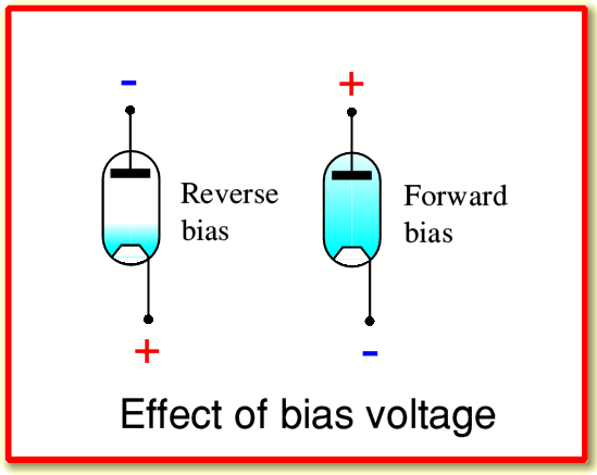
The diagram above illustrates what happens when we apply a potential difference between the anode and the cathode. (Note that the heater is working, and the cathode is hot, but the heater isn’t shown.)
When we apply a voltage to make the anode positive with respect to the cathode we attract the electrons in the vacuum space towards the anode, and push them away from the cathode. This has the effect of making it easier for electrons to reach the anode. It also tends to reduce the density of electrons near the cathode, making it easier for more to ‘boil off’ the cathode. The result is that when we apply a potential difference this way around we tend to increase the rate at which electrons flow from cathode to anode. Thus, making the anode positive relative to the cathode increases the current flow. This sign of applied potential is called “Forward Bias”.
When we apply a voltage the other way around, and make the anode negative with respect to the cathode we repel the electrons in the vacuum space away from the anode, and make it harder for them to escape the cathode. Since the anode isn’t hot, it does not tend to release any electrons itself. The result is that when we apply a potential difference this way around we tend to make it even harder for any electrons to cross the vacuum space. The current flow is therefore almost zero. This sign of applied potential is called “Reverse Bias”.
If you look in a basic textbook on Physics or Electronics you may find an analysis of the behaviour of a pair of metal plates, one of which is heated. This leads to an algebraic expression that describes how the current tends to vary with the applied voltage. This has the form
where  is the anode-cathode current,
  is the potential difference between anode and cathode, and
  is a factor whose value depends on the size and shape of the anode, cathode, etc. This relationship is called Child’s Law.
However we should treat this result with caution as it makes some simplifying assumptions that often do not describe a practical valve very well. It also ignores the small ‘leakage’ of current we described earlier that occurs even if we don’t apply any external voltage. Despite these words of caution, the basic behaviour is that when forward biassed, the current tends to rise rapidly as we increase the voltage, and when reverse biassed, the current is almost nil. This is the basic rectifying behaviour which we associated with diodes in electronics. The variation of current with voltage is also nonlinear, and the device does not obey Ohm’s Law. Hence we can also use valve diodes as nonlinear devices.
It is quite common for the makers to put two actual diode arrangements into one vacuum container, and hence make a valve that functions as a pair of diodes. Typically, the circuit symbols for these show two anodes and one cathode. since that is the usual arrangement.
The Triode
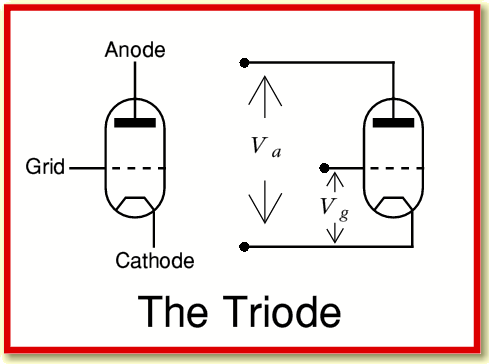
Diodes are useful for tasks like rectifying, but to obtain gain and be able to amplify signals different forms of valve were developed. The simplest of these is the Triode. As the name implies, this has three electrodes whereas a diode has just two. The extra electrode is called a “Grid” as this describes its usual physical form.
The above diagram represents a triode arrangement. The grid is a fine mesh or winding of wire, placed in between the anode and cathode. Usually it is located much nearer to the cathode than the anode.
We can now consider applying potential differences in two ways:
-
 , a potential difference between anode and cathode.
-
 , a potential difference between grid and cathode.
These are applied as indicated in the above diagram.
Electrons in the space charge region near the cathode now experience an electric field which has two components - that due to the anode, and that due to the grid.
The electric field produced by a potential difference depends on how close together the objects are located. Since the grid is close to the cathode, a given voltage on the grid exerts much more force on electrons near the cathode than would the same voltage on the more distant anode. This means the current is much more sensitive to changes in the grid voltage than to changes in the anode voltage.
To understand what this implies we can use an example. Let’s assume that we have a triode where the distance between the anode and cathode is 10 mm, but the grid is just 1 mm from the cathode. We start off by applying a potential of +200 Volts to the anode with respect to the cathode. This has the effect of producing an electric field near the cathode of +200/10 = 20 Volts/mm which tends to try and accelerate electrons in the space towards the anode. The result of this field will be to tend to set up a steady flow of electrons, and hence a large anode-cathode current.
However, if we now apply a potential of, say, -10 Volts to the grid with respect to the cathode this produces an electric field near the cathode of -10/1 = -10 Volts/mm.
One of the basic rules of electromagnetic fields in space is “Field Superposition”. This means that we can just add together the fields produced by different elements or objects provided we get the signs and directions correct. In this case, the values above mean that we’d get a resulting field near the cathode of 20 - 10 = 10 Volts/mm. The result of the -10 Volts on the grid is almost as if we had turned down the anode voltage attracting the electrons by 100 Volts! Indeed, if we’d increased the grid voltage to -20 Volts, the electrons near the cathode would see no net electric field due to the presence of the anode and grid, and the flow from cathode to anode would drop to almost zero.
As a result of the field superposition, and having the grid near the cathode, we can therefore use relatively small voltage variations on the grid to control, vary, or even cut off, the anode-cathode current level. This behaviour is the basis of how we can then use valves like a Triode to amplify signals. A small change in grid voltage can be used to produce much larger variations in voltage and current at the anode.
We can use a modified version of the Child’s Law equation to estimate what we can expect the anode-cathode current we get to approximately be
when forward biassed, and zero – as with the diode – when reverse biassed. However in this case ‘forward bias’ means that 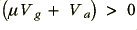 , so depends on both the applied potentials.
The  value is often called the valve’s “Amplification Factor”. The value for a given design of valve will depend on various details – the obvious one being that we get a higher value if we can hold the grid very near to the cathode. However there are all kinds of detailed effects and problems I have ignored here, which also limit what can be made. In practice, real triodes tend to have amplification factor values somewhere in the range 10 – 100.
Since we try to put the grid near the cathode, we can expect it to be in or near the region where the space charge density is significant. Hence there is a tendency for the grid to pick up a flow of electrons from the space charge cloud of electrons, unless we apply a large enough negative voltage to the grid to push the electrons away, close to the cathode, and cut off the flow through the valve. This is leads to one of the possible difficulties of trying to make a triode with a high amplification factor. It tends to mean putting the grid closer to the cathode, where the charge density is high, and more electrons then tend to hit the grid.
In normal use, most of the electrons tend to fly through the gaps between the wires of the grid, but some will hit the grid and be lost from the anode-cathode current. Cutting down on the size of the wires in the grid, or placing them further apart may reduce the grid current. Alas, it also tends to weaken the ability of the grid to apply an electric field to its surroundings, so reducing the amplification factor for that reason.