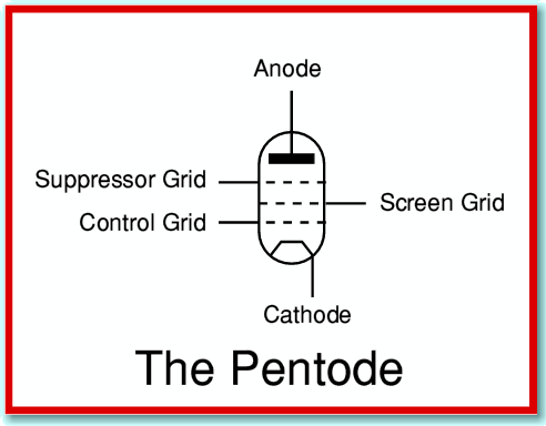
If you have an interest in a topic like audio/hi-fi you may already know that valve amplifiers are still popular with some enthusiasts. These don’t all use triodes. Instead, some use Pentodes. As the name implies, a pentode has five electrodes – a cathode, an anode, and three grids. These extra grids are included to try and deal with some of the practical drawbacks of the triode.
The usual symbol for a pentode valve is shown above. The ‘Control Grid’ is the electrode that acts in the same way as the single grid in a triode. i.e. it is where we input the signal that controls the anode-cathode current. The ‘Suppressor Grid’ and ‘Screen Grid’ are the additional electrodes. To understand their purpose let’s consider some of the practical problems that arise with the triode valve. We can do this by using the circuits shown below.
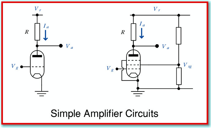
The above illustration shows two simple arrangements that we might use as experimental amplifiers. In each case the intention is that we use the control (signal) grid for our input and the anode for our output. Usually, we want the amplifier to provide a reasonably large voltage gain. This means that when we change the input voltage,  , by a small amount we wish to arrange that the output,
  , changes by a much larger amount. The arrangement on the left uses a triode. That on the right uses a pentode. Note that the above circuits aren’t actually very useful as practical amplifiers, so if you look in textbooks you will see various, more complex, arrangements which differ in detail from the above. However the simple circuits illustrated above will serve to show the functions of the new grids.
Since we have arranged for both circuits to show a high gain, we can expect that when we change  by a small amount,
  , will change by a much larger amount. Now in practice the electrodes are all conducting objects placed close together. This means there will be some capacitance between them. The result is that to change the potential differences between the electrodes we have to charge/discharge these capacitances. This means that we may have to provide quite high input currents to the control grid if we wish to change the grid voltage (and hence also the anode voltage very quickly. This tends to restrict the ability of the triode to amplify at high frequencies.
The pentode’s Screen Grid is used as an electrostatic screen in between the control grid and the anode. This grid is held at a steady potential midway between that on the anode and the cathode or control grid, so tends to ‘shield’ the control grid from seeing the changes in potential of the anode. Hence it tends to reduce the effective capacitance between the control grid and the anode. The result is that less current is needed to drive the input signal variations of the control grid, making it easier for the valve to be used at higher frequencies than a triode.
Some valves only have two grids – the control grid and the screen grid – and are called tetrodes. However simple tetrodes have their own problems. Some of the electrons which travel from the cathode and hit the anode may arrive with enough kinetic energy to knock free some electrons from the anode. These may then interfere with the valve operation in various ways. Any that remain around the anode may produce an unwanted negative space charge which will deter fresh electrons from arriving from the cathode. Others may strike the grids, or even the cathode, again producing unwanted flows of charge that degrade the operation of the valve. This problem can become particularly noticable if we allow the variations of the anode voltage to swing the anode’s potential to being negative compared with the screen grid. When this happens we could get quite a large unwanted flow of electrons from the anode to the screen, and the result is a distortion or ‘kink’ in the way the anode voltage varies as we change the input voltage on the control grid.
The Suppressor Grid is employed to catch electrons that have been released from the anode. This grid uses just a few wires, placed near the anode, and usually connected to the cathode potential. Most of the electrons coming from the cathode fly through the gaps in all the grids as they have been given a lot of kinetic energy by the cathode-anode potential difference. So most of them whizz past the wires in the grids. However most of the electrons knocked out of the anode will have a relatively small amount of kinetic energy, As a result, they tend either to fall back to the anode, or drift into the nearest grid – which is now the suppressor grid. Having done this, they don’t have any effect on the input current required to drive the control grid, and have little effect on the valve’s gain, etc.
The above explanations are quite simplified, but should indicate why pentodes may be preferred over triodes of we wish to obtain high gain and high bandwidth. The details of the bias arrangements in practical circuits will vary according to the requirements (and the preferences of the designer!) but the basic idea is that:
- The Control Grid is normally used to input the signal to be amplified
- The Suppressor Grid is normally connected to the same potential as the cathode so as to sweep away any unwanted electrons liberated from the anode.
- The Screen Grid is normally connected to a steady potential somewhere in between the anode and cathode potentials, and shields the input signal from seeing a large input capacitance.
In practice it is quite common for a single valve ‘envelope’ to contain two actual valve devices. This helps keep down the weight and size of the devices, and may allow them to share a heating arrangement for their cathodes.
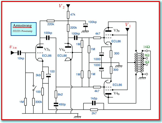
The above shows an example of a simple, perhaps old-fashioned, hi-fi power amplifier design from the 1950’s/1960’s. The details of this circuit are too complex to deal with here, but if you examine the circuit diagram you can see that although it shows four gain devices, they are actually paired. The valves shown as V3A and V3B are in the same glass envelope and sold as an ‘ECL86’. Similarly, V4A and V4B are another ECL86.
You will also see that the above diagram does show the output devices (V3B and V4B) as only having two grids, which implies they are tetrodes. In fact audio output valves often employed another form of valve called the ‘Beam Tetrode’. The most well-known examples in the UK being the KT66 and KT88. These tetrodes only have connections for four electrodes, but they include a pair of ‘beam forming plates’ that direct the electron flows. These plates are internally connected to the cathode, and serve the same function as the suppressor grid. The ‘KT’ in the type numbers for the KT66 and KT88 stands for ‘Kinkless Tetrode’. It lets us know that although these valves only apparently have four electrodes, they have been modified internally to remove the ‘kink’ in the transfer curve which I mentioned earlier.
The above is only a very brief introduction to the family of thermionic valves. Although they have largely been replaced by solid-state devices in most applications, valves are still used for special purposes, and some audio enthusiasts continue to prefer valve amplifiers for listening to music.