In my last Investigation I looked at the audio properties of loudspeaker cables. My main conclusion was that a cable with low series resistance and inductance might well be the preferred choice. However that article just looked at the effects of the cable at audio frequencies and ignored some details that might be significant. I did mention in the previous article that some amplifiers can be upset by some load impedances. This can cause problems ranging from bursts of instability to changes in the distortion performance. To see why cables matter we need to examine the whole amplifier-cable-load system and widen the range of frequencies being considered
Figure 1
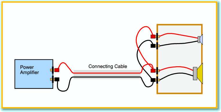
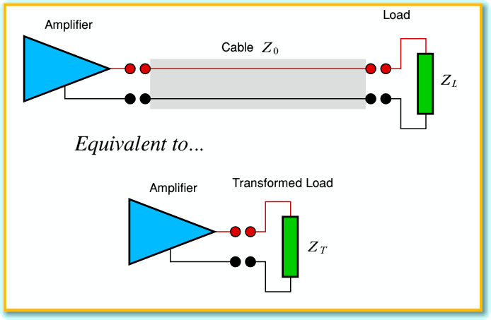
As explained in the previous article, we can regard the connecting cable as a transmission line with a characteristic impedance whose (frequency dependent) value depends on the physical details of the cable[1]. The systems we are interested will look like the arrangement shown in Figure 1. Electronic engineers can represent this using the circuit shown in Figure 2.
Figure 2
One of the properties of transmission line is that it can alter the apparent impedance of the load (speaker) as seen by the signal source (amplifier). This was the idea behind the ‘8 Ohm’ cable Monitor Audio sold back in the 1970s. Using a cable ‘matched’ to an 8 Ohm load we’d find that – no matter how long the cable – the speaker would still look like an 8 Ohm load. However this only works if the cable and load really do have the same impedance. As soon as their values differ the cable acts like a sort of ‘transformer’ and changes the load presented to the amplifier output.
Figure 3
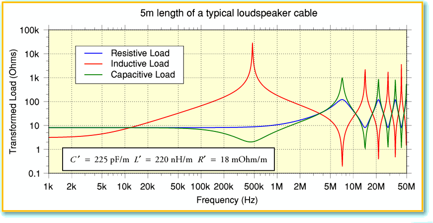
Figure 3 shows some typical results caused by mismatch between load and cable. Here I have plotted the transformed impedance presented to the amplifier when using a 5 metre run of loudspeaker cable. I chose a cable with low inductance listed in the survey done by Martin Colloms[2]. Note that the frequency range covered extends up to 50 MHz. This is well above being audible, so looking at such high frequencies might seem pointless. But some amplifier designs may struggle when presented with such a load. The problem is that most audio power amplifiers use devices and designs whose internal gain starts to fall away in the region between around 1 MHz and 50 MHz. The delays in their feedback loop can become significant at these frequencies, and their output impedance also tends to rise. For some, being connected to a load like that shown in Figure 3 could mean the amplifier bursts into full power oscillations – typically at a few MHz. Even when this doesn’t happen, the combination might not work as intended because the amplifier is upset by the loading.
Figure 4
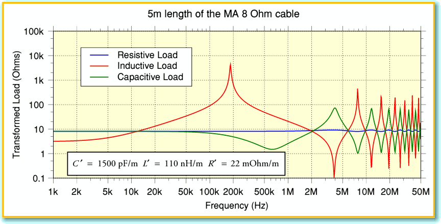
Figure 4 shows the results for an ‘8 Ohm’ cable using the values determined by James Moir[3]. You can see that with an 8 Ohm resistive load (blue line) the problem essentially disappears when using this cable. Alas, the same can’t be said when the loudspeaker load is either capacitive (green line) or inductive (red line). Indeed, in these cases the ‘8 Ohm’ cable gives worse results than the previous example. In particular, with an inductive load Figure 4 shows a drop down to below 0·1 Ohms (!) at the dip of a narrow resonance at around 3 MHz. This is a particularly nasty feature for some amplifiers. Oscillations prompted at that frequency might draw high currents and cause amplifier failure! It isn’t surprising that this type of cable did cause headaches for some amplifier manufacturers.
The problem here is that any given cable impedance can’t possibly ‘match’ every loudspeaker. And as we know from speaker measurements, their impedance properties vary from one model to another. To make things worse, people rarely even think of measuring speaker impedances in the 1 - 50 MHz range! Worse still, the transformed impedance experienced by the amplifier will also depend on the cable type and length.
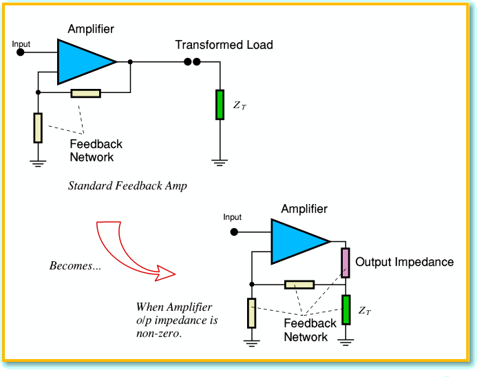
Some designers are particularly aware of these problems, and have tried to tackle them. For example Denis Morecroft of DNM has developed and sold some specific types of cable designed with these effects in mind. The basis of his argument is that the cable essentially become a component in the feedback network of the power amplifier, and so can affect its behaviour. This idea may seem strange at first, but can be understood by looking at Figure 5.
Figure 5
It doesn’t really matter if you aren’t familiar with electronics diagrams, although Figure 5 will show the situation clearly to those who can read the runes! The vital point is that as soon as we accept that the circuits inside the feedback loop have a non-zero output impedance then the circuit is influenced by the cable and load. We then get behaviour where the transformed load can affect performance. Alas, there is a tendency for the amplifier’s output impedance to rise as we increase the frequency well above the normal audio band. So the system can then become more sensitive to the loading!
To try and deal with the problem, Morecroft specifically chooses his speaker cables to have two unusual features. One is that the spacing between the live and ground conductors is wide. The other is the use of single-strand (i.e. ‘solid’) conductors of a particular – fairly small – diameter. At audio frequencies the consequence is that the series inductance and resistance are higher than when using most thick bundled multistranded cables. Both of these choices run contrary to the conclusions of my previous article. But does Morcroft’s approach have advantages?...
Figure 6
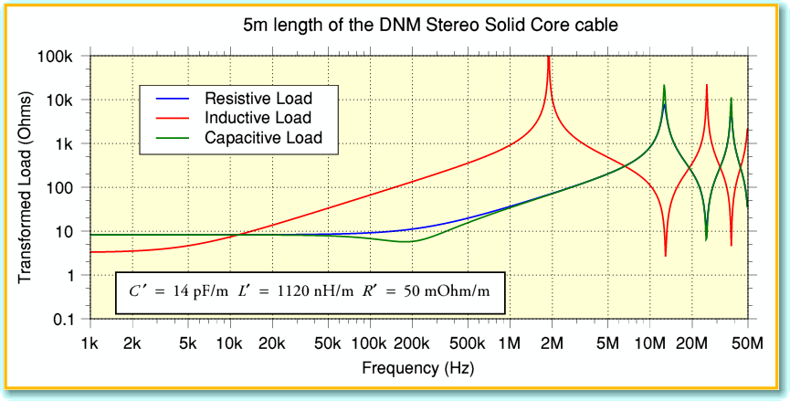
Figure 6 illustrates the transformed impedance we can expected to be produced when using the DNM Stereo Solid Core cable in the same situation as used for the previous results. As the conductors are solid core we can expect the cable’s internal impedance (often called ‘skin effect’) to alter its series resistance as we go to high frequencies. I therefore included this in the analysis. Comparing Fig 6 with the previous examples one particular point is worth noting. The first resonant ‘dip’ is now above 10MHz, and it only drops to about 3 Ohms as a minimum. Whereas the other cables produced smaller minimum impedances at lower frequencies. Hence Morecroft’s approach may well mean the amplifier sees a less ‘difficult’ load at these high frequencies and reduces any tendency for the amp to misbehave.
Figure 7
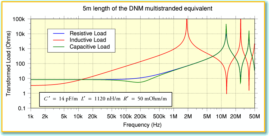
For comparison, Figure 7 shows what we might get if the DNM cable used conventional multistranded woven conductors. Multistranding keeps the series resistance low at radio frequencies. This might seem a good thing to do, but one result is a dip down to a much lower minimum – more like 1 Ohm – at just over 10 MHz. Quite a marked fall in the minimum value the amp would see! So comparing Figures 6 and 7 indicates that solid core conductors can indeed help avoid low resonant impedances at radio frequencies – although the precise results in practice will of course depend on the speaker load and cable lengths.
On the basis of the above, it is reasonable to present such cables as being worth using. However we should also now ask if they have any potential drawbacks, or if there are alternatives which mean they ‘solve’ a problem we can avoid without their use...
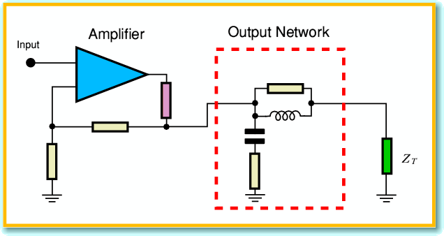
If you have been reading audio magazines for some time, or have designed any power amplifiers, you will have come across the term ‘unconditionally stable’. This means the amplifier is built so that it won’t oscillate whatever load is presented to it. This can be achieved in various ways. One of the simplest methods, widely used over the years, is to use an output network of the kind shown in Figure 8.
Figure 8
Arrangements like this are sometimes called a ‘Zobel Network’ – although that term may strictly apply only to the capacitor and resistor in series, also sometimes called a ‘snubber’ by some engineers. Whatever the name, this network sets out to achieve two purposes. At low (audio) frequencies the series inductor has a low impedance and is essentially a direct link from amplifier to cable and loudspeaker. At low frequencies the capacitor acts like an open circuit. So at low frequencies the amplifier sees itself connected to the load. But at higher (ultrasonic) frequencies the inductor tends to block any flow of current to the load, and the capacitor acts like a low impedance. At radio frequencies the amplifier is now connected to the cable and load via a resistance. The result is that the amplifier is isolated from the load at high frequencies, and instead sees a resistance chosen by the amplifier designer. This tends to prevent the amplifier noticing any resonant dips and peaks in the load at radio frequencies.
The big advantage of this network is that the amplifier designer can include it inside the amplifier box. It will then have these effects regardless of what loudspeaker and cables the user chooses. This does at least bring some peace of mind to the amplifier designer already worried about the scurrilously activities of SCAMP[4], and increases the chance your new amplifier won’t self destruct! Indeed, it might be worth pointing out that if loudspeaker manufacturers all ensured their units had an agree impedance then we might avoid these problems entirely. But I won’t hold my breath waiting for this given the headaches they inflict on amplifier designers at audio frequencies. SCAMP seem to rule at RF as well as audio frequencies!
Figure 9
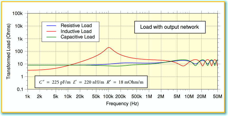
Figure 9 shows what load the amplifier sees when an output network is used with the same cable as Figure 3. If you compare them, you can see that without the network the cable produced dips down to well below 1 Ohm. Using the network, the dips don’t go much below 8 Ohms. Hence the amplifier is protected from the RF behaviour of the cable and speaker load.
Figure 10
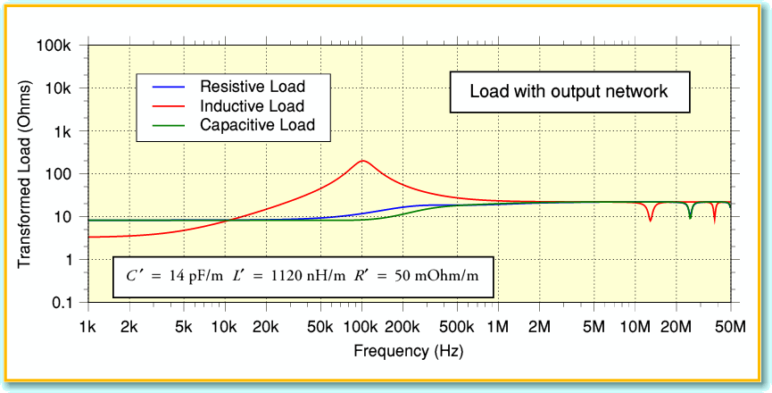
Figure 10 shows what happens when we use the network with the DNM cable. In this case the dips and peaks almost disappear!
The use of such a network isn’t ideal as we have deliberately introduced some series impedance into the amplifier output, and this will add to any series impedances of the chosen cables. The result may be to alter the audio frequency response, or alter the behaviour in some other way. But the network does give the amplifier designer a ‘fire and forget’ way to protect the amplifier from some potentially annoying RF problems. Not only they don’t have to lay awake in bed at night, worrying about what might happen with all the wilder combinations of cables and speakers. The series inductor inside the amplifier box also helps to block RF signals from sources like mobile phones from getting into the amplifier via the speaker leads!
The network isn’t the only method for making an amplifier insensitive to RF load. Various other ways to tackle or avoid this problem have been proposed. For example, it has been suggested that a network be fitted at the loudspeaker end of the cable to try and provide a load that matches the cable[5]. Unfortunately, that technique only works properly if we know the impedances of both the specific cable run and the loudspeaker being used. SCAMP seem to have done their best to rule this solution out...
From the results shown, it is clear that cables of the type provided by DNM could be worth considering if your amp may be RF sensitive. In such cases it can give the amplifier an easier life, and promote better performance. However, if your amplifier is not bothered by RF impedance problems, then a cable simply chosen on the basis of having low series resistance and inductance may be a better bet. In addition to experimenting, one way to assess this is to see if your amp is stated to be ‘unconditionally stable’ by the makers, and – in particular – if it uses an output inductor and a network of the kind shown in Figure 8. If it does, then it may be better to avoid cables like the DNM ones as the result may simply be a needless increase in the series impedance, altering the frequency response. Alas, this can be hard to assess as it all depends on details you may not have been told by the manufacturers. Even unconditional stability doesn’t guarantee that something else like the distortion performance is unaffected by RF loading – or mobile phone signals!
My personal preference still tends to be for thicker cables, with closely spaced bundles of stranded wire. But I know the amplifiers I use have output networks and aren’t bothered by RF loading. If you don’t know this is the case for your choice of amplifiers, then it may be worth experimenting with DNM cable or something similar. More generally, it should be clear from this article that – in principle at least – the geometry of the cable arrangement can affect the behaviour, so I hope to look at that in more detail in a future article. All being well, I also hope to obtain some measurements of the impedance behaviour of some cables to compare with the analysis and see how well theory agrees with reality!
18th Jun 2008
2300 Words
Jim Lesurf
[1] You can find more on how these work via various links from
http://www.st-andrews.ac.uk/~www_pa/Scots_Guide/audio/Analog.html
[2] The Cable Survey: Part 2 Speaker Wires. M. Colloms Hi Fi News pp 50-53 July 1990
[3] Loudspeaker Cables James Moir Hi Fi News pp 67-75 May 1979
[4] SCAMP. Jim Lesurf Hi Fi News pp 100-102 May 2007
[5] For example, look at http://www.sound.westhost.com/cable-z.htm
